Table of Contents
Advertisement
Advertisement
Table of Contents

Related Manuals for Yaesu FT-4VR


Summary of Contents for Yaesu FT-4VR
- Page 1 VHF FM TRANSCEIVER FT-4V FT-4V Operating Manual...
-
Page 2: Table Of Contents
Contents Introduction ........................1 About this manual ......................1 Quick Guide ........................2 Controls & Connections ....................3 Transceiver ........................3 Display ..........................5 The Keypad Functions ....................7 Safety Precautions (Be Sure to Read) ................8 Preparation ........................11 Installing the Antenna .................... -
Page 3: Introduction
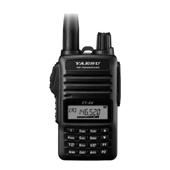
Introduction Thank you for purchasing this Yaesu product. m FT-4VR/VE is a handheld transceiver for operation in the 144 MHz Ama- teur radio bands. m A Bridged Transless (BTL) amplifier provides One Full Watt of Audio in spite of small size. -
Page 4: Quick Guide
Quick Guide Names and display of Controls PWR/VOL Knob PTT Switch Microphone MONI/T-CALL Switch Function Key (Frequency up and down) Key [# VFO ] Key Normal operation (VFO Mode) Operating Frequency VFO-A S Meter / PO Meter ① Turning the Power ON 1. -
Page 5: Controls & Connections
Controls & Connections Transceiver ⑧ ① ⑨ ⑩ ② ⑭ ⑪ ③ ⑮ ⑦ ④ ⑫ ⑤ ⑥ ⑬ ⑦ ① Strap attachment ( ② Antenna Jack(SMA) ( PTT Switch ( • Press and hold the PTT switch to transmit, and release it to receive. ③... - Page 6 Function Key ( Pressing the Function key activates the “Secondary” key function. ⑥ Press and hold the Function key enters the Set mode. In the Set mode, pressing the Function key defines and saves the set- ting. ⑦ Battery pack( PWR/VOL Knob •...
-
Page 7: Display
Display Frequency / Memory Tag / PAGER Set Mode Item VFO-A/B Memory Channel Number Home Channel Display Memory Bank S Meter: Displays the received signal strength PO Meter: Displays the transmit power level Icon Description Priority Memory Channel Memory channel registered as a skip memory. Repeater Shift Direction Split Memory (two different frequencies) : Appears when the tone encoder function. - Page 8 Icon Description Appears when the Dual Receive (DW) function is enabled. Appears when the APO (Automatic Power-Off) func- tion is enabled. Appears when the bell function is enabled. Appears when the lock function is enabled. Appears when the Memory Bank function is en- abled.
-
Page 9: The Keypad Functions
The Keypad Functions Primary Function (Press Key) Third Secondary Function Function (Press and Inputting (Press F + Memory Recall Hold for over Memory Tag Key) one second) A c t i v a t e s t h e A c t i v a t e s t h e Deactivates the “Secondary”... -
Page 10: Safety Precautions (Be Sure To Read)
Yaesu is not liable for any failures or problems caused by the use or misuse of this product by the purchaser or any third party. Also, Yaesu is not liable for damages caused through the use of this product by the purchaser or any third party, except in cases where ordered to pay damages under the laws. - Page 11 Do not disassemble or make any alteration to this product. Do not use any battery charger An injury, electric shock, or failure may which is not specified by Yaesu. result. A fire or failure can result. Keep the terminals of the battery When transmitting, keep the trans- pack clean.
- Page 12 Improper installation may cause the The case may be deformed or discol- FT-4VR/VE to fall or drop, resulting in ored. an injury or damage. Do not place a heavy object on the Do not place this transceiver in a power cord of the AC adapter.
-
Page 13: Preparation
Preparation Installing the Antenna 1. Turn the antenna clockwise until it is secured. • Do not hold or twist the upper part of the antenna Hold the thick base of the antenna when installing or removing it. To do so may break the conductors inside the antenna. -
Page 14: Supplied Accessories And Options
Supplied Accessories and Options Supplied Accessories • Rechargeable Li-Ion Battery Pack (7.4V, 1,750mAh) SBR-28LI • AC adapter SAD-20 * • Operating Manual (this manual) • Rapid Charger • SBR-28LI Manual SBH-22 • Antenna SRA-16N • Belt Clip SHB-18 * : Depending on the transceiver version. If any item is missing, contact the dealer from which the transceiver was purchased. -
Page 15: Operation
z Approximate Operating Time and Remaining Charge Level Indication Approximate operating time for the transceiver with the fully charged lithi- um-Ion battery pack (SBR-28LI), and the indication of the remaining charge level of the battery is shown in the below table: Frequency band Band in Use Charge Level Indication (Icon) -
Page 16: Changing The Frequency Step
Changing the Frequency Step Pressing the [] key or [] key, the frequency step may be changed. Nor- mally, the factory default setting will provide a good frequency step. Press and hold Press the Press the Function key the Function key →... -
Page 17: Changing The Transmission Power Level
Changing the Transmission Power Level Press and hold or Press the Press the Function key the Function key → → (Enters the Set mode) (Select Set Mode "40 TX PWR") (Confirms the setting) 1. Press the [] or [] to select one of the following transmission power levels. -
Page 18: Programmable Key [ P1 ] / [ P2 ]
Programmable key [ P1 ] / [ P2 ] [P1] and [P2] keys may be used for the followings: • One Touch Recall of a preferred setting • One Touch Recall of the Mode settings (1) One touch recall of the preferred status 1. To store a preferred setting, Press and hold one of the [P1] or [P2] keys. -
Page 19: Repeater Operation
MONI/T-CALL switch, and use the PTT switch to activate the transmitter thereafter. If needed, the FT-4VR (USA/Asian version), may be set to access repeaters which require a 1750 Hz burst tone by setting the MONI/T-CALL switch to serve as a “Tone Call” switch instead. To change the configuration of the... -
Page 20: Using The Memory
Using the Memory The FT-4VR/VE transceiver incorporates Large-capacity memory channels that can register the operating frequency, communication mode, and other operational information. • 200 Memory Channels • 2 Home Channels • 10 pairs PMS Memory channel Each memory channel can store the following information: •... -
Page 21: Registering To Memory Channels
• To recall Memory Channel #200, enter “200”. To recall Programmable Memory channels “L01/U01” through “L10/U10” enter “201/202” through “219/220”. • The FT-4VR/VE may be set to operated only in the registered memory channels. Press and hold the MONI/T.CALL key and the PTT switch simultaneously, while turning the radio ON to enter the preferred operating mode. -
Page 22: Clearing Memories
Clearing Memories Press and hold Press the Press the Function key the Function key → → (Enters the Set mode) (Select Set Mode "20 MEM DEL") (Confirms the setting) 1. Press the [] key or [] key to select the memory channel from which the data is to be cleared. -
Page 23: Memory Channel Scanning
Memory Channel Scanning The receiver may be set to scan memory channels: 1. While operating in the VFO mode, press the [ MR] key to enter the Mem- ory mode. 2. Press and hold the [▲] key or [▼] key. Scanning starts of the memory channels begins. If the scanner halts on an incoming signal, the back light will turn ON and the decimal point between the “MHz”... -
Page 24: Split Memory
For additional details on the following functions, refer to the Advanced Manual which may be downloaded from the Yaesu website. Split Memory Two different frequencies, one for receive and another for transmit, may be stored in one memory channel. Using Memory Tag Memory name tags may be assigned to the memory channels and home channels. -
Page 25: Programmed Vfo Scan
Programmed VFO Scan The scan condition may be selected for VFO scanning. 1. Press the [#VFO] key to enter the VFO mode. 2. Press and hold the [#VFO] key. 3. Press the [▲] or [▼] key to select the bandwidth for Programmed VFO scanning. Display Description BAND... -
Page 26: Weather Alert Scan (In The Usa)
NOAA Alert Tone while operating using VFO scan or Memory channel scan. When the Weather Alert Scan feature is engaged, the FT-4VR/VE will check the Weather Broadcast Channels for activity every five seconds while scan- ning. -
Page 27: Convenient Functions
Convenient Functions VOX Operation The VOX system provides automatic transmit/receive switching based on voice input. With the VOX system enabled, you do not need to press the PTT switch in order to transmit. Optional VOX earpiece microphone (SSM-512B) is also available. VFO Split Mode Two different frequencies, one for receive and another for transmit, may be operated. -
Page 28: Using Set Mode
• On some setting screens, key operation is different than described in the above steps (For example, inputting the characters, etc.). Refer to the Advance manual. For additional details, refer to the Advanced Manual which may be down- loaded from the Yaesu website Tables of Set Mode Operations Selectable options Set Mode... - Page 29 Selectable options Set Mode Description (Options in bold are the item default settings) ID= _ _ _ _ _ _ (6 characters) CW WRT Sets the CW ID during ARTS operation. default: blank DC VLT Displays the voltage. (Voltage) 104 DCS CODEs / OFF 10 DCS.COD Sets the DCS CODE RX and TX.
- Page 30 Selectable options Set Mode Description (Options in bold are the item default settings) OFF / S-1 / S-2 / S-3 / S-4 RF SQL Adjusts the RF Squelch threshold level. /S-5 / S-6 / S-8 / S-FULL RPT.ARS Turns the ARS function on/off. ARS.ON / ARS.OFF OFF / 0.025MHz –...
-
Page 31: Restoring To Defaults (Reset) / Setting The Preferred Operating Mode
Restoring to Defaults (Reset) / Setting the Preferred Operating Mode The following reset or preferred operating modes may be selected. 1. Turn the transceiver OFF. 2. Press and hold the MONI/T.CALL key and the PTT switch simultaneously, while turning the transceiver ON. 3. -
Page 32: Specifications
Specifications ● General Frequency Range RX: 136 - 174 MHz TX: 136 - 174 MHz (Asian version) 144 - 146 MHz (European version) 144 - 148 MHz (USA version) FM Broadcast: 65 - 108 MHz Channel Steps : 5/10/12.5/15/20/25/50/100kHz Mode of Emission : F2D, F3E, F2A Frequency Stability : ±2.5 ppm (−20 °C to +60 °C [−4 °F to +140 °F]) - Page 33 ● Receiver Circuit Type : Direct-conversion Sensitivity : 0.2 μV for 12 dB SINAD (140 - 150 MHz, NFM) Selectivity (-6 dB/-60 dB) : FM, NFM ±25 kHz / 12.5 kHz AF Output : 800 mW (16 Ω for THD 10 % 7.4 V DC) internal speaker 800 mW (16 Ω for THD 10 % 7.4 V DC) external speaker Specifications are subject to change without notice, and are guaranteed within the 144 MHz amateur bands only.
- Page 34 “Warranty Period.” ( the “Limited Warranty” ) . Limitations of Warranty: A. YAESU MUSEN is not liable for any express warranties except the Limited Warranty described above. B. The Limited Warranty is extended only to the original end-use purchaser or the person receiving this product as a gift, and shall not be extended to any other person or transferee.
- Page 35 3. Upon receipt of this product, returned in accordance with the procedures described above, by the YAESU Authorized Service Center, all reasonable efforts will be expended by YAESU MUSEN to cause this product to con- form to its original specifications. YAESU MUSEN will return the repaired product ( or a replacement product ) free of charge to the original purchas- er.
- Page 36 1. Changes or modifications to this device that are not expressly approved by YAESU MUSEN could void the user’s authorization to operate this device. 2. This device complies with part 15 of the FCC Rules. Operation is subject to the following two conditions: (1) This device may not cause harmful interference, and (2) this device must accept any interference including received, interference that may cause undesired operation.
- Page 37 Note...
- Page 38 Note...
- Page 39 EU Declaration of Conformity We, Yaesu Musen Co. Ltd of Tokyo, Japan, hereby declare that this radio equipment FT-4VE is in full compliance with EU Radio Equipment Directive 2014/53/EU. The full text of the Declaration of Conformity for this product is available to view at http://www.yaesu.com/jp/red...
- Page 40 Copyright 2018 YAESU MUSEN CO., LTD. All rights reserved. No portion of this manual may be reproduced without the permission of YAESU MUSEN CO., LTD. YAESU MUSEN CO., LTD. Tennozu Parkside Building 2-5-8 Higashi-Shinagawa, Shinagawa-ku, Tokyo 140-0002 Japan YAESU USA 1803M-AC-1 6125 Phyllis Drive, Cypress, CA 90630, U.S.A.
Need help?
Do you have a question about the FT-4VR and is the answer not in the manual?
Questions and answers