Table of Contents
Advertisement
Quick Links
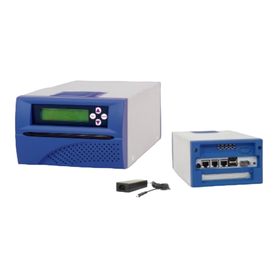
PNA-2413
2U Communication Appliance Server with Three LANs and
One PCI Expansion Slot
Processor
Flexible processor support ranging
®
®
from the Intel
Celeron
processor at
566 MHz to the Pentium
®
III processor
at 866 MHz with support for
66/100/133 MHz Processor System
Bus (PSB)
Memory
- Support for 100 and 133MHz SDRAM
- 512 MB SODIMM maximum memory
I/O Ports
- 3 Intel ® 82559ER Ethernet LAN
connect interf a ce
- Two USB ports
- One RS-232
Storage Device
- One 3.5" Hard disk Bay
- Embedded DOM socket
PCI Expansion
One PCI expansion slot
Ordering Guide
PNA-2413-0000
2U communication appliance server with three LANs, one PCI expansion slot
and EZIO (CPU and RAM not included)
Specification
LCD Panel
2 x 16 characters EZIO-100 module
LCD panel
LEDs
8 user self defined programming LEDs
Power
External 70W AC/DC power adapter
Operating Environment
- Tempature: 5 to 45˚C
- Humidity: 20% to 90% RH
Storage Environment
- Tempature: 5 to 70˚C
- Humidity : 5% to 95% RH
Dimension
144(W) x 260(D) x 88(H)mm
5.7"(W) x 10.2"(W) x 3.5"(H)
Safety
CE/FCC
Highlights
Designed based on Intel
®
concept architecture platform
Three Embedded Intel
®
10/100
Ethernet for easy I/O configuration
Embedded storage capability design
for DOM usage
16 x 2 characters EZIO-100 LCD
panel module makes the installation
and maintenance easier and more
efficient
Tailor-made redirect to console BIOS
allows users to operate system via a
com port
Both desktop and Rack-mount form
factor with good system ventilation
design
3 units stacked side-by-side fit a 19"
2U rack
One PCI expansion slot
One SODIMM socket
One optional VGA output
Proof of
Advertisement
Table of Contents

Related Manuals for Portwell PNA-2413

Summary of Contents for Portwell PNA-2413
- Page 1 PNA-2413 2U Communication Appliance Server with Three LANs and One PCI Expansion Slot Highlights Specification Designed based on Intel ® Proof of concept architecture platform LCD Panel Processor Three Embedded Intel ® 10/100 2 x 16 characters EZIO-100 module Flexible processor support ranging...
- Page 2 PNA-2413 Communications Appliance User′s Manual Revision: 010 Por twell Inc. 3F, No. 92, Sec. 1, Nei-Hu Rd., Taipei 114, Taiwan, R.O.C. Headquarter: +886-2-2799-2020 FAX: +886-2-2799-1010 http://www.portwell.com.tw Email: info@mail.portwell.com.tw Item NO: B8980670...
-
Page 3: Table Of Contents
Table of Contents Chapter 1 Introduction ......................2 About This Manual ..................2 Manual Organization ..................2 Technical Support Information................ 2 Chapter 2 Getting Started ....................3 Included Hardware ..................3 Before You Begin ................... 3 The Chassis ....................4 Opening the Chassis .................. -
Page 4: Chapter 1 Introduction
1.3 Technical Support Information Users may find helpful tips or related information on Portwell's web site: http://www.portwell.com.tw. A direct contact to Portwell's technical person is also available. For further support, users may also contact Portwell’ s headquarter in Taipei or your local distributors. -
Page 5: Chapter 2 Getting Started
Chapter 2 Getting Started This section describes how the hardware installation and system settings should be done. 2.1 Included Hardware The following hardware is included in your kit: PPAP-200 Communication Appliance System Board AC to 15V DC adapter One null serial port cable 2.2 Before You Begin To prevent damage to any system board, it is important to handle it with care. -
Page 6: The Chassis
( Fig. 2-4 ). Fig. 2-3 Remove bolts from COM port Fig. 2-4 Take off the screws on back panel 2. Turn PNA-2413 over. Press both metal clips hard to loose the plastic back cover ( Fig. 2-5 ). - Page 7 The plastic back panel can then be taken off ( Fig. 2-6 ). Fig. 2-6 Take off the plastic back panel Fig. 2-7 Pull out the inner steel case 4. Pull out the inner steel case ( Fig. 2-7 ). 5.
-
Page 8: Installing Or Removing A Sodimm
2.5 Installing or Removing a SODIMM Follow these steps to upgrade RAM module: 1. Install the system memory by pulling the socket’ s arm and pressing it into the slot gently. ( Fig. 2-12, 2-13 ) Fig. 2-12 The memory slot Fig. -
Page 9: Remove And Install Battery
1. Connect the power source to DOM ( Fig. 2-17, 2-18 ). Fig. 2-17 Connect power to DOM Fig. 2-18 DOM power connection 2. The completed installation of DOM is shown as Fig. 2-19 . Fig. 2-19 Completion of DOM power connection 2.7 Remove and Install Battery 1. -
Page 10: Remove And Install Hdd
Follow the steps below to install the HDD: Before a HDD can be installed onto PNA-2413. PPAP-200 must be taken off from the chassis. 1. Remove EZIO COM port cable ( Fig. 2-22 ) and the power connector from EZIO ( Fig. 2-23 ). - Page 11 5. Connect the IDE cable and power connector to HDD ( Fig. 2-27 ). 6. Fasten both screws back to lock HDD onto chassis ( Fig. 2-28 ). Fig. 2-27 Connect power and IDE cable to Fig. 2-28 Install into chassis 7.
-
Page 12: Remove And Install Pci Card
2.9 Remove and Install PCI card One PCI slot is available to PNA-2413. Follow the steps below for installation: 1. The PCI slot is located on the back of the board ( Fig. 2-32 ). 2. The back of the PCI card should be against the back of PPAP-200 ( Fig. 2-33, 2-34 ). - Page 13 6. If there is an add-on PCI card, the original metal bracket needs to be removed ( Fig. 2-38 ). ¬ Á 7. Apply downward force ( Fig. 2-39 ) and then slide toward the front panel ( Fig. 2-39 ).
-
Page 14: Product Specifications
PCI IDE Interface: • Support two high-speed 16C550 compatible UARTs with 16-byte Serial Ports: T/R FIFOs • (Optional) Support LCD/Key pad module (Portwell proprietary) • USB Interface: Support two USB ports for high speed I/O peripheral devices • Auxiliary I/O Interfaces:... -
Page 15: Hardware Configuration Setting
2.11 Hardware Configuration Setting This section gives the definitions and shows the positions of jumpers, headers and connectors. All of the configuration jumpers on PPAP-200 are in the proper position. The default settings set by factory are marked with a star ( ★ ). Jumpers In general, jumpers on PPAP-200 system board are used to select options for certain features. - Page 16 Connectors Devices are connected through these connectors which includes IDE, COM Port etc… Connector Function Remark Serial ports connector Shrouded pin header Reset push button FDC connector Secondary IDE connector Primary IDE connector Parallel port connector Chassis fan connector Chassis fan connector D-SUB 9 Serial ports connector Supply power to...
- Page 17 J3: FDC Connector PIN No. Signal Description PIN No. Signal Description Ground Density0# Ground Ground Density1# Ground INDEX# Ground MOA# Ground DSB# Ground DSA# Ground MOB# Ground DIR# Ground STEP# Ground Ground Ground TRACK0# Ground RDATA# Ground HEAD# DSKCHG# J4/J5: IDE Connector PIN No.
- Page 18 J6: Parallel Connector PIN No. Signal Description PIN No. Signal Description Strobe# AFD# Data 0 ERR# Data 1 INIT# Data 2 SLIN# Data 3 Ground Data 4 Ground Data 5 Ground Data 6 Ground Data 7 Ground ACK# Ground BUSY Ground Ground SLCT...
- Page 19 J13/J14/J15: Ethernet Connector PIN No. Signal Description PIN No. Signal Description Termplane Termplane Termplane Termplane J17: Power Jack Connector PIN No. Signal Description +15V Ground Ground J18: PCI Bus Connector PIN No. Signal Description PIN No. Signal Description PTRST# PTCK +12V Ground PTMS...
-
Page 20: Install A Different Processor
AD17 AD16 C_BE#2 Ground FRAME# IRDY# Ground TRDY# DEVSEL# Ground Ground STOP# PLOCK# PERR# SDONE SBO# SERR# Ground C_BE#1 AD15 AD14 Ground AD13 AD12 AD11 AD10 Ground Ground C_BE#0 Ground Ground ACK64# REQ64# 2.12 Install a Different Processor Install CPU 1. -
Page 21: Use A Client Computer
If users use a headless PNA-2413, which has no mouse/keyboard and VGA output connected to it, the console may be used to communicate with PNA-2413. To access PNA-2413 via the console, Hyper Terminal is one of the choices. Follow the steps below for the setup: 1. - Page 22 4. Please make the port settings to Baud rate 19200, Parity None, Data bits 8, Stop bits 1 5. Turn on the power of PNA-2413, after following screen was shown 6. You can then see the boot up information of PNA-2413 7.
-
Page 23: Chapter 3 Operation Guide
Chapter 3 Operation Guide 3.1 Brief Guide of PPAP-200 PPAP-200 is a Communication Appliance computing board based on Intel 815E chipset technology. PPAP-200 has three on-board LAN ports to serve communication appliances, such as Firewall, which needs three Ethernet ports to connect external network (internet), demilitarized zone and internal network. -
Page 24: System Architecture
3.2 System Architecture The following illustration of block diagram will show you how PPAP-200 gives you a highly integrated system solution. The most up-to-date system architecture of PPAP-200 includes two main VLSI chips. It contains 82815GMCH and 82801BA ICH2 to support FC-PGA Celeron/Pentium III processor, SODIMM, PCI bus interface, USB port, SMBus communication, and Ultra DMA/100 IDE Master.
Need help?
Do you have a question about the PNA-2413 and is the answer not in the manual?
Questions and answers