
Related Manuals for Daikin FCAHG71GVEB


Summary of Contents for Daikin FCAHG71GVEB
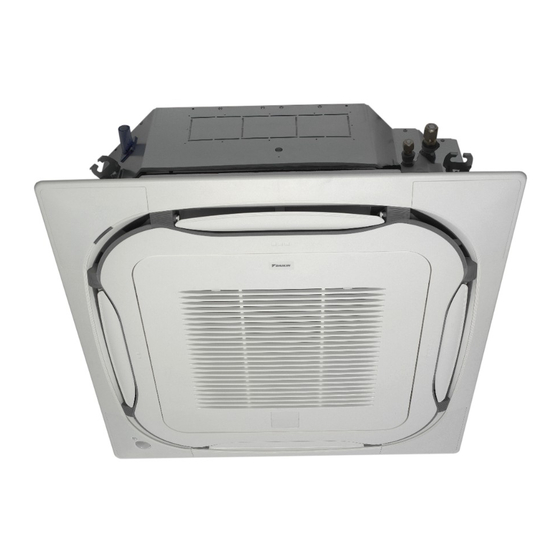
- Page 1 Installer and user reference guide Split system air conditioners FCAHG71GVEB FCAHG100GVEB Installer and user reference guide FCAHG125GVEB English Split system air conditioners FCAHG140GVEB...
- Page 2 3P480520-3A...
-
Page 3: Table Of Contents
Table of Contents 8 Commissioning Table of Contents Overview: Commissioning............20 Precautions when commissioning ..........20 Checklist before commissioning..........20 To perform a test run..............20 1 General safety precautions Error codes when performing a test run ........21 About the documentation ............1.1.1 Meaning of warnings and symbols...... -
Page 4: General Safety Precautions
Only use operation manual, and the wiring instruction sheet. accessories, optional equipment and spare parts made or approved by Daikin. Before performing maintenance and service tasks, read the service manual. For more information, see the installer and user reference guide. -
Page 5: Installation Site
Make sure installation, servicing, maintenance and repair ▪ Do NOT sit, climb or stand on the unit. comply with instructions from Daikin and with applicable legislation (for example national gas regulation) and are NOTICE executed only by authorised persons. -
Page 6: Refrigerant
1 General safety precautions Ceiling-mounted Wall-mounted Floor-standing Contains fluorinated greenhouse gases unit unit unit m (kg) m (kg) m (kg) GWP: xxx <1.224 — <1.224 — <1.224 — 1.225 0.956 1.225 1.43 1.225 12.9 1.25 1.87 16.8 2.44 22.0 1.63 GWP ×... -
Page 7: Brine
1 General safety precautions DANGER: RISK OF EXPLOSION CAUTION Pump down – Refrigerant leakage. If you want to pump When the refrigerant charging procedure is done or when down the system, and there is a leakage in the refrigerant pausing, close valve refrigerant... -
Page 8: About The Documentation
WARNING Daikin website (publicly accessible). ▪ After finishing the electrical work, confirm that each ▪ The full set of latest technical data is available on the Daikin electrical component and terminal inside the electrical extranet (authentication required). components box is connected securely. -
Page 9: Indoor Unit
4 About the units and options ▪ Bring the packed unit as close as possible to its final installation About the units and options position to prevent damage during transport. Overview: About the units and Indoor unit options 3.2.1 To unpack and handle the unit This chapter contains information about: Use a sling of soft material or protective plates together with a rope ▪... -
Page 10: System Layout
5 Preparation To avoid condensation and water dripping out of the unit. If Preparing installation site the temperature or the humidity is beyond these conditions, safety devices may be put in action and the air conditioner Do NOT install the unit in places often used as work place. In case may not operate. -
Page 11: Preparing Refrigerant Piping
5 Preparation ▪ Choose a location where the hot/cold air discharged from the unit If air flow direction… Then B or the operation noise, will NOT disturb anyone. FCAHG71 FCAHG100~140 ▪ Air flow. Make sure nothing blocks the air flow. All-round ≤3.5 m ≤4.2 m... -
Page 12: Refrigerant Piping Insulation
6 Installation ▪ Connecting the refrigerant piping. 5.3.2 Refrigerant piping insulation ▪ Checking the refrigerant piping. ▪ Use polyethylene foam as insulation material: ▪ Charging refrigerant. ▪ with a heat transfer rate between 0.041 and 0.052 W/mK (0.035 ▪ Connecting the electrical wiring. and 0.045 kcal/mh°C) ▪... -
Page 13: Guidelines When Installing The Drain Piping
6 Installation Washer (accessories) ▪ Installation guide. Use the installation guide to determine the Hanger bracket (attached to the unit) correct vertical position. ▪ Paper pattern for installation (upper part of the packing). Use the paper pattern to determine the correct horizontal positioning. It contains the necessary dimensions and centers. - Page 14 6 Installation ▪ Rising piping. If necessary to make the slope possible, you can install rising piping. ▪ Drain hose inclination: 0~75 mm to avoid stress on the piping and to avoid air bubbles. ▪ Rising piping: ≤300 mm from the unit, ≤675 mm perpendicular to the unit.
-
Page 15: Connecting The Refrigerant Piping
6 Installation NOTICE Take the following precautions on refrigerant piping into account: ▪ Avoid anything but the designated refrigerant to get mixed into the refrigerant cycle (e.g. air). ▪ Only use R32 or R410A when adding refrigerant. ▪ Only use installation tools (e.g. manifold gauge set) that are exclusively used for R32 or R410A installations to withstand the pressure and to prevent foreign materials... -
Page 16: Pipe Bending Guidelines
6 Installation Piping size Tightening Flare Flare shape (mm) torque (N•m) dimensions (A) (mm) (mm) 90° ±2 Ø9.5 33~39 12.8~13.2 Ø15.9 63~75 19.3~19.7 Refrigerant piping R=0.4~0.8 Part to be brazed Taping Manual valve Pressure-reducing valve 6.3.4 Pipe bending guidelines Nitrogen ▪... -
Page 17: Connecting The Electrical Wiring
6 Installation Connecting the electrical wiring Wire type Installation method Stranded conductor wire with round 6.4.1 About connecting the electrical wiring crimp-style terminal Typical workflow Connecting the electrical wiring typically consists of the following stages: a Terminal Making sure the power supply system complies with the b Screw electrical specifications of the units. -
Page 18: Configuration
7 Configuration 1~ 50 Hz WARNING 220-240 V Provide adequate measures to prevent that the unit can be used as a shelter by small animals. Small animals that make contact with electrical parts can cause malfunctions, smoke or fire. 5 Reattach the service cover. ▪... - Page 19 7 Configuration Individual setting in a simultaneous operation system If the distance to the floor is (m) Then We recommend using the optional user interface to set the slave FCAHG71 FCAHG100~140 unit. ≤2.7 ≤3.2 13 (23) Perform the following steps: 2.7<x≤3.0 3.2<x≤3.6 2 Change the second code number to 02 to perform individual...
-
Page 20: Commissioning
8 Commissioning Commissioning There are NO missing phases or reversed phases. The system is properly earthed and the earth terminals Overview: Commissioning are tightened. The fuses or locally installed protection devices are This chapter describes what you have to do and know to installed according to this document, and have not been commission the system after it is installed. -
Page 21: Error Codes When Performing A Test Run
▪ A subset of the latest technical data is available on the regional menu is displayed. Daikin website (publicly accessible). ▪ The full set of latest technical data is available on the Daikin extranet (authentication required). FCAHG71~140GVEB Installer and user reference guide Split system air conditioners 4P482875-1 –... -
Page 22: Piping Diagram: Indoor Unit
11 Technical data 11.1 Piping diagram: Indoor unit Liquid pipe connection Gas pipe connection Heat exchanger Installer and user reference guide FCAHG71~140GVEB Split system air conditioners 4P482875-1 – 2017.03... -
Page 23: Wiring Diagram
11 Technical data 11.2 Wiring diagram Unified Wiring Diagram Legend For applied parts and numbering refer to the wiring diagram sticker supplied on the unit. Part numbering is realized by Arabic numbers in ascending order for each part and is represented in the overview below by symbol “*” in the part code. CIRCUIT BREAKER PROTECTIVE EARTH CONNECTION... -
Page 24: For The User
Contact details: NOTICE DAIKIN INDUSTRIES CZECH REPUBLIC s.r.o. U Nové Hospody 1/1155, 301 00 Plzeň Skvrňany, Czech Republic Do not use the system for other purposes. In order to avoid any quality deterioration, do not use the unit for cooling precision instruments, food, plants, animals or works of art. -
Page 25: 15 Operation
15 Operation Hot start Operation In order to prevent cold air from blowing out of an indoor unit at the start of heating operation, the indoor fan is automatically stopped. 15.1 Operation range The display of the user interface shows . -
Page 26: Adjusting The Air Flow Direction
16 Energy saving and optimum operation ▪ Turn off the main power supply switch to the unit when the unit is 15.4 Adjusting the air flow direction not used for longer periods of time. If the switch is on, it consumes electricity. -
Page 27: Cleaning The Air Filter, Suction Grille, Air Outlet And Outside Panels
17 Maintenance and service 17.1 Cleaning the air filter, suction grille, air outlet and outside panels 17.1.1 To clean the air filter When to clean the air filter: ▪ Rule of thumb: Clean every 6 months. If the air in the room is extremely contaminated, increase the cleaning frequency. -
Page 28: Maintenance Before A Long Stop Period
17 Maintenance and service 17.3 Maintenance before a long stop 17.5 After-sales service and warranty period 17.5.1 Warranty period E.g., at the end of the season. ▪ This product includes a warranty card that was filled in by the ▪ Let the indoor units run in fan only operation for about half a day in dealer at the time of installation. -
Page 29: Shortened Maintenance And Replacement Cycles
18 Troubleshooting ▪ Normal use without frequent starting and stopping of the unit. Troubleshooting Depending on the model, we recommend not starting and stopping the machine more than 6 times/hour. If one of the following malfunctions occur, take the measures shown below and contact your dealer. -
Page 30: Symptoms That Are Not System Malfunctions
19 Relocation 18.1.7 Symptom: Noise of air conditioners 18.1 Symptoms that are NOT system (Indoor unit) malfunctions ▪ A "zeen" sound is heard immediately after the power supply is The following symptoms are NOT system malfunctions: turned on. The electronic expansion valve inside an indoor unit starts working and makes the noise. - Page 31 Optional equipment Equipment made or approved by Daikin that can be combined with the product according to the instructions in the accompanying documentation. Field supply Equipment not made by Daikin that can be combined with product according instructions accompanying documentation.
- Page 32 4P482875-1 2017.03...
Need help?
Do you have a question about the FCAHG71GVEB and is the answer not in the manual?
Questions and answers