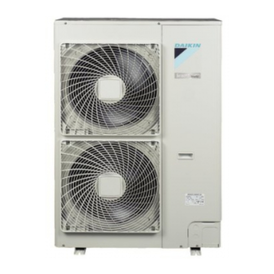
Summary of Contents for Daikin RZQ71D3V1B
- Page 1 INSTALLATION MANUAL Split System air conditioners RZQ71D3V1B RZQ100D9V1B RZQ125D9V1B RZQ140D9V1B RZQ100B9W1B RZQ125B9W1B RZQ140B9W1B...
- Page 2 B 2 B 2 D 2 D 2 D 2 D 2 L 1 L 1 B 1 B 1 L 2 L 2 D 1 D 1 B 2 B 2 D 2 D 2 D 2 D 2 L 1 L 1 B 1 B 1 L 2 L 2...
- Page 3 3PW61025-1...
-
Page 4: Table Of Contents
Make certain that all electrical work is carried out by qualified OTHER DAMAGE TO THE EQUIPMENT. BE SURE ONLY personnel according to the local laws and regulations and this TO USE ACCESSORIES MADE BY DAIKIN WHICH ARE installation manual, using a separate circuit. SPECIFICALLY DESIGNED FOR USE WITH THE Insufficient capacity of the power supply circuit or improper... -
Page 5: Before Installation
In Europe, EN378 provides the necessary guidance for this logbook. RZQ71D3V1B + RZQ100~140D9V1B + RZQ100~140B9W1B Installation manual Split System air conditioners 4PW60930-1... -
Page 6: Selecting Installation Site
150 mm of the underside of the unit) or case the user may be required to take adequate use a drain plug kit (option) in order to measures. avoid drainwater dripping. (See figure). Installation manual RZQ71D3V1B + RZQ100~140D9V1B + RZQ100~140B9W1B Split System air conditioners 4PW60930-1... -
Page 7: Precautions On Installation
(optional). Make sure the drain works properly. ≥50 (100) ≥1000 (2000) ≥100 (200) ≥500 (1000) RZQ71D3V1B + RZQ100~140D9V1B + RZQ100~140B9W1B Installation manual Split System air conditioners 4PW60930-1... -
Page 8: Refrigerant Pipe Size And Allowable Pipe Length
Pipe Ø of piping material Minimal thickness t (mm) 6.4 / 9.5 / 12.7 0.80 15.9 1.00 19.1 1/2H O=Annealed 1/2H=Half hard Only use annealed material for flare connections. Installation manual RZQ71D3V1B + RZQ100~140D9V1B + RZQ100~140B9W1B Split System air conditioners 4PW60930-1... -
Page 9: Precautions On Refrigerant Piping
Pinch the pipe Outdoor unit Less than a month Pinch or tape the pipe Regardless of the Indoor unit period Great caution is needed when passing copper tubes through walls. RZQ71D3V1B + RZQ100~140D9V1B + RZQ100~140B9W1B Installation manual Split System air conditioners 4PW60930-1... -
Page 10: Refrigerant Piping
Make sure to keep the valve open during operation. The names of parts of the stop valve are shown in the figure. Service port stop valve Field piping connection Valve cover Installation manual RZQ71D3V1B + RZQ100~140D9V1B + RZQ100~140B9W1B Split System air conditioners 4PW60930-1... - Page 11 Ø12.7 50~60 N•m 16.2~16.6 R=0.4~0.8 Tightening torque Ø15.9 63~75 N•m 19.3~19.7 Liquid pipe 13.5~16.5 N•m Gas pipe 22.5~27.5 N•m Check for refrigerant leakage after tightening the cap. RZQ71D3V1B + RZQ100~140D9V1B + RZQ100~140B9W1B Installation manual Split System air conditioners 4PW60930-1...
-
Page 12: Evacuating
–100.7 kPa. After keeping the system under that condition for more than one hour, check if the vacuum gauge rises or not. If it rises, the system may either contain moisture inside or have leaks. Installation manual RZQ71D3V1B + RZQ100~140D9V1B + RZQ100~140B9W1B Split System air conditioners 4PW60930-1... -
Page 13: Charging Refrigerant
– – b (G1+G2) 30=(5+54) 30=29 Ø6.4 R2=0.9 kg For future servicing, mark with a circle the selected amount on the Refrigerant charge amount=R=R1+R2=0.0+0.9=0.9 kg tables below RZQ71D3V1B + RZQ100~140D9V1B + RZQ100~140B9W1B Installation manual Split System air conditioners 4PW60930-1... - Page 14 Make sure that stop valves both on liquid and gas side are open and be sure to operate the unit in cooling operation during test run. Installation manual RZQ71D3V1B + RZQ100~140D9V1B + RZQ100~140B9W1B Split System air conditioners 4PW60930-1...
-
Page 15: Electrical Wiring Work
Follow the electric wiring diagram for electrical wiring works. Form the wires and fix the cover firmly so that the cover may be fit in properly. RZQ71D3V1B + RZQ100~140D9V1B + RZQ100~140B9W1B Installation manual Split System air conditioners 4PW60930-1... -
Page 16: Test Operation
(1) European/International Technical Standard setting the limits for harmonic currents produced by equipment connected to public low-voltage systems with input current >16 A and ≤75 A per phase. Installation manual RZQ71D3V1B + RZQ100~140D9V1B + RZQ100~140B9W1B Split System air conditioners 4PW60930-1... -
Page 17: Disposal Requirements
30 minutes. In case of a wireless remote controller, execute the test run only after having installed the indoor unit decoration panel with infra- red receiver first. RZQ71D3V1B + RZQ100~140D9V1B + RZQ100~140B9W1B Installation manual Split System air conditioners 4PW60930-1... -
Page 18: Wiring Diagram
Y2S......Solenoid valve R1•R2.....Resistor Z1C~Z5C ....Noise filter R1T ......Thermistor (air) Z1F~Z4F....Noise filter R2T ......Thermistor (coil) (for W1 models only) R2T ......Thermistor (discharge) (for V1 models only) Installation manual RZQ71D3V1B + RZQ100~140D9V1B + RZQ100~140B9W1B Split System air conditioners 4PW60930-1... - Page 19 NOTES NOTES...
- Page 20 4PW60930-1...


Need help?
Do you have a question about the RZQ71D3V1B and is the answer not in the manual?
Questions and answers