Table of Contents
Advertisement
Available languages
Available languages
Quick Start
Z170A SLI PLUS
Thank you for purchasing the MSI
motherboard.
®
This Quick Start section provides demonstration diagrams about
how to install your computer. Some of the installations also provide
video demonstrations. Please link to the URL to watch it with the web
browser on your phone or tablet. You may have even link to the URL
by scanning the QR code.
Kurzanleitung
Z170A SLI PLUS
Danke, dass Sie das MSI
Motherboard gewählt
®
haben. Dieser Abschnitt der Kurzanleitung bietet eine Demo zur
Installation Ihres Computers. Manche Installationen bieten auch
die Videodemonstrationen. Klicken Sie auf die URL, um diese
Videoanleitung mit Ihrem Browser auf Ihrem Handy oder Table
anzusehen. Oder scannen Sie auch den QR Code mit Ihrem Handy,
um die URL zu öffnen.
Présentation rapide
Merci d'avoir choisi la carte mère MSI
Z170A SLI
PLUS. Ce manuel
®
fournit une rapide présentation avec des illustrations explicatives
qui vous aideront à assembler votre ordinateur. Des tutoriels vidéo
sont disponibles pour certaines étapes. Cliquez sur le lien fourni
pour regarder la vidéo sur votre téléphone ou votre tablette. Vous
pouvez également accéder au lien en scannant le QR code qui lui
est associé.
Быстрый старт
Z170A
Благодарим вас за покупку материнской платы MSI
®
SLI
PLUS. В этом разделе представлена информация, которая
поможет вам при сборке комьютера. Для некоторых этапов
сборки имеются видеоинструкции. Для просмотра видео,
необходимо открыть соответствующую ссылку в веб-браузере
на вашем телефоне или планшете. Вы также можете выполнить
переход по ссылке, путем сканирования QR-кода.
I
Quick Start
Advertisement
Chapters
Table of Contents

Related Manuals for MSI Z170A SLI PLUS


Summary of Contents for MSI Z170A SLI PLUS
- Page 1 Videoanleitung mit Ihrem Browser auf Ihrem Handy oder Table anzusehen. Oder scannen Sie auch den QR Code mit Ihrem Handy, um die URL zu öffnen. Présentation rapide Merci d’avoir choisi la carte mère MSI Z170A SLI PLUS. Ce manuel ®...
- Page 2 Installing a Processor/ Installation des Prozessors/ Installer un processeur/ Установка процессора http://youtu.be/bf5La099urI Quick Start...
- Page 3 Installing DDR4 memory/ Installation des DDR4-Speichers/ Installer une mémoire DDR4/ Установка памяти DDR4 http://youtu.be/T03aDrJPyQs Quick Start...
- Page 4 Connecting the Front Panel Header/ Anschließen der Frontpanel-Stiftleiste/ Connecter un connecteur du panneau avant/ Подключение разъемов передней панели http://youtu.be/DPELIdVNZUI HDD LED + Power LED + HDD LED - Power LED - Reset Switch Power Switch Reset Switch Power Switch JFP1 Reserved No Pin JFP1...
- Page 5 Installing the Motherboard/ Installation des Motherboards/ Installer la carte mère/ Установка материнской платы Quick Start...
- Page 6 Installing SATA Drives/ Installation der SATA-Laufwerke/ Installer le disque dur SATA/ Установка дисков SATA http://youtu.be/RZsMpqxythc Quick Start...
- Page 7 Installing a Graphics Card/ Einbau der Grafikkarte/ Installer une carte graphique/ Установка дискретной видеокарты http://youtu.be/mG0GZpr9w_A Quick Start...
- Page 8 Connecting Peripheral Devices/ Peripheriegeräte/ Connecter un périphérique anschliessen/ Подключение периферийных устройств VIII Quick Start...
- Page 9 Connecting the Power Connectors/ Stromanschlüsse anschliessen/ Connecter les câbles du module d’alimentation/ Подключение разъемов питания http://youtu.be/gkDYyR_83I4 JPWR1 JPWR2 Quick Start...
- Page 10 Power On/ Einschalten/ Mettre sous-tension/ Включение питания Quick Start...
-
Page 11: Table Of Contents
Contents Safety Information ....................2 Specifications ......................3 Rear I/O Panel ......................8 LAN Port LED Status Table ................. 8 Audio Ports Configuration ..................8 Overview of Components ..................10 CPU Socket ....................... 11 DIMM Slots ......................12 PCI_E1~6: PCIe Expansion Slots..............13 JAUD1: Front Audio Connector ................. 14 SATA1~6: SATA 6Gb/s Connectors .............. -
Page 12: Safety Information
Safety Information ● The components included in this package are prone to damage from electrostatic discharge (ESD). Please adhere to the following instructions to ensure successful computer assembly. ● Ensure that all components are securely connected. Loose connections may cause the computer to not recognize a component or fail to start. -
Page 13: Specifications
ECC UDIMM memory (non-ECC mode) ● Supports Intel Extreme Memory Profile (XMP) ® * Please refer to www.msi.com for more information on compatible memory. ● 3x PCIe 3.0 x16 slots (support x16/x0/x4, x8/x8/x4 modes) Expansion Slots ● 3x PCIe 3.0 x1 slots ●... - Page 14 Continued from previous page ● ASMedia ASM1142 Chipset ® ▶ 1x USB 3.1 Gen2 Type-C port on the back panel ● Intel Z170 Chipset ® ▶ 6x USB 3.1 Gen1 (SuperSpeed USB) ports (2 ports on the back panel, 4 ports available through the internal USB connector) ▶...
- Page 15 Continued from previous page ● 1x 24-pin ATX main power connector ● 1x 8-pin ATX 12V power connector ● 6x SATA 6Gb/s connectors ● 2x USB 2.0 connectors (supports additional 4 USB 2.0 ports) ● 2x USB 3.1 Gen1 connectors (supports additional 4 USB 3.1 Gen1 ports) ●...
- Page 16 ● MILITARY CLASS 4 ▶ Military Class Component ▶ Military Class Stability and Reliability ESD Protection EMI Protection Humidity Protection MSI Exclusive Circuit Protection Features High Temperature Protection Steel Armor PCIe Slots VGA Armor Slot ● COMMAND CENTER ▶ System Monitor ▶...
- Page 17 Continued from previous page ● DDR4 Boost Support ▶ Dual-Channel DDR4 Memory Support ▶ Isolated DDR4 Circuit Design ▶ DDR4 XMP Ready ● PCI Express 3.0 Support Specification ▶ 2-Way Nvidia SLI Support Highlights ▶ 3-Way AMD CrossFire Support ● USB 3.1 Gen2 Ready ▶...
-
Page 18: Rear I/O Panel
Rear I/O Panel Audio Ports USB 3.1 Gen 1 PS/2 Mouse USB 3.1 Gen 2 Type-C USB 2.0 DVI-D PS/2 Keyboard LAN Port LED Status Table Link/ Activity LED Speed LED Status Description Status Description No link 10 Mbps connection Yellow Linked Green... - Page 19 Audio jacks to headphone and microphone diagram Audio jacks to stereo speakers diagram AUDIO INPUT Audio jacks to 7.1-channel speakers diagram AUDIO INPUT Rear Front Side Center/ Subwoofer Rear I/O Panel...
-
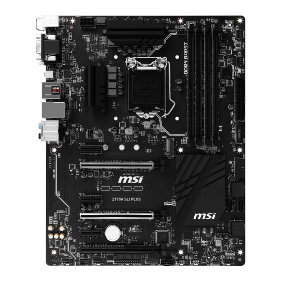
Page 20: Overview Of Components
Overview of Components DIMM3 DIMM2 DIMM4 SYSFAN1 DIMM1 CPUFAN1 JPWR2 CPU Socket CPUFAN2 SYSFAN3 EZ Debug LED JPWR1 JUSB3 PCI_E1 M2_1 JUSB4 PCI_E2 SATA1_2 PCI_E3 SATA4 SATA3 PCI_E4 SATA5_6 PCI_E5 JCI1 JBAT1 PCI_E6 JFP1 JAUD1 JFP2 SYSFAN2 JUSB1 JCOM1 JUSB2 JLPT1 JTBT1* JTPM1... -
Page 21: Cpu Socket
Always unplug the power cord from the power outlet before installing or removing ● the CPU. Please retain the CPU protective cap after installing the processor. MSI will deal ● with Return Merchandise Authorization (RMA) requests if only the motherboard comes with the protective cap on the CPU socket. -
Page 22: Dimm Slots
DIMM Slots DIMM1 DIMM3 Channel A Channel B DIMM2 DIMM4 Memory module installation recommendation DIMM4 DIMM4 DIMM3 DIMM2 DIMM2 DIMM2 DIMM1 Important Always insert memory modules in the DIMM2 slot first. ● ● Due to chipset resource usage, the available capacity of memory will be a little less than the amount of installed. -
Page 23: Pci_E1~6: Pcie Expansion Slots
PCI_E1~6: PCIe Expansion Slots PCI_E1: PCIe 3.0 x1 slot PCI_E2: PCIe 3.0 x16 slot PCI_E3: PCIe 3.0 x1 slot PCI_E4: PCIe 3.0 x8 slot PCI_E5: PCIe 3.0 x1 slot PCI_E6: PCIe 3.0 x4 slot Multiple graphics cards installation recommendation Important For a single PCIe x16 expansion ●... -
Page 24: Jaud1: Front Audio Connector
JAUD1: Front Audio Connector This connector allows you to connect audio jacks on the front panel. MIC L Ground MIC R Head Phone R MIC Detection SENSE_SEND No Pin Head Phone L Head Phone Detection SATA1~6: SATA 6Gb/s Connectors These connectors are SATA 6Gb/s interface ports. Each connector can connect to one SATA device. -
Page 25: M2_1: M.2 Slots
M2_1: M.2 Slots Important Intel RST only supports PCIe M.2 SSD with UEFI ROM, ® does not support Legacy ROM. Video Demonstration Watch the video to learn how to Install M.2 module. http://youtu.be/JCTFABytrYA Installing M.2 module Remove the screw from the base screw. -
Page 26: Jpwr1~2: Power Connectors
JPWR1~2: Power Connectors These connectors allow you to connect an ATX power supply. JPWR2 Ground +12V Ground +12V Ground +12V Ground +12V +3.3V +3.3V +3.3V -12V Ground Ground PS-ON# Ground Ground Ground JPWR1 Ground Ground PWR OK 5VSB +12V +12V +3.3V Ground Important... -
Page 27: Jusb1~2: Usb 2.0 Connectors
JUSB1~2: USB 2.0 Connectors These connectors allow you to connect USB 2.0 ports on the front panel. USB0- USB1- USB0+ USB1+ Ground Ground No Pin Important ● Note that the VCC and Ground pins must be connected correctly to avoid possible damage. -
Page 28: Jfp1, Jfp2: Front Panel Connectors
JFP1, JFP2: Front Panel Connectors These connectors connect to the switches and LEDs on the front panel. JFP1 HDD LED + Power LED + HDD LED - Power LED - Reset Switch Power Switch Reset Switch Power Switch Reserved No Pin Speaker - Buzzer + JFP2... -
Page 29: Jci1: Chassis Intrusion Connector
JCI1: Chassis Intrusion Connector This connector allows you to connect the chassis intrusion switch cable. Normal Trigger the chassis intrusion event (default) Using chassis intrusion detector Connect the JCI1 connector to the chassis intrusion switch/ sensor on the chassis. Close the chassis cover. Go to BIOS >... -
Page 30: Jlpt1: Parallel Port Connector
JLPT1: Parallel Port Connector This connector allows you to connect the optional parallel port with bracket. RSTB# AFD# PRND0 ERR# PRND1 PINIT# PRND2 LPT_SLIN# PRND3 Ground PRND4 Ground PRND5 Ground PRND6 Ground PRND7 Ground ACK# Ground BUSY Ground Ground SLCT No Pin JCOM1: Serial Port Connector This connector allows you to connect the optional serial port with bracket. -
Page 31: Cpufan1~2, Sysfan1~3: Fan Connectors
CPUFAN1~2, SYSFAN1~3: Fan Connectors Fan connectors can be classified as PWM (Pulse Width Modulation) Mode and Voltage Mode. PWM Mode fan connectors provide constant 12V output and adjust fan speed with speed control signal. Voltage Mode fan connectors control fan speed by changing voltage. -
Page 32: Jbat1: Clear Cmos (Reset Bios) Jumper
JBAT1: Clear CMOS (Reset BIOS) Jumper There is CMOS memory onboard that is external powered from a battery located on the motherboard to save system configuration data. If you want to clear the system configuration, set the jumper to clear the CMOS memory. Keep Data Clear CMOS/ Reset BIOS... -
Page 33: Bios Setup
Press Delete key, when the Press DEL key to enter Setup Menu, F11 to enter Boot Menu message appears on the screen during the boot process. Use MSI FAST BOOT application. Click on GO2BIOS button and choose OK. The ●... -
Page 34: Resetting Bios
Updating BIOS Updating BIOS with M-FLASH Before updating: Please download the latest BIOS file that matches your motherboard model from MSI website. And then save the BIOS file into the USB flash drive. Updating BIOS: Press Del key to enter the BIOS Setup during POST. -
Page 35: Overclocking Menu
Overclocking Menu This menu is for advanced users who want to overclock the motherboard. Important ● Overclocking your PC manually is only recommended for advanced users. Overclocking is not guaranteed, and if done improperly, it could void your warranty ● or severely damage your hardware. - Page 36 Ring Ratio [Auto] ▶ Sets the ring ratio. The valid value range depends on the installed CPU. ▶ Adjusted Ring Frequency Shows the adjusted Ring frequency. Read-only. ▶ GT Ratio [Auto] Sets the integrated graphics ratio. The valid value range depends on the installed CPU.
- Page 37 CPU Base Clock Apply Mode [Auto]* ▶ Sets the applying mode for adjusted CPU base clock. [Auto] This setting will be configured automatically by BIOS. [Next Boot] CPU will run the adjusted CPU base clock at next boot. [Immediate] CPU runs the adjusted CPU base clock immediately. [During Boot] CPU will run the adjusted CPU base clock during boot.
- Page 38 CPU Core/ GT Voltage Mode [Auto]* ▶ Selects the control mode for CPU Core/ GT voltages. [Auto] This setting will be configured automatically by BIOS. [Adaptive Mode] Sets the adaptive voltage automatically for optimizing the system performance. [Override Mode] Allows you to set the voltage manually. [Offset Mode] Allows you to set the offset voltage and select the voltage offset mode.
- Page 39 DIMMx Memory SPD ▶ Press Enter to enter the sub-menu. The sub-menu displays the information of installed memory. Read only. CPU Features ▶ Press Enter to enter the sub-menu. ▶ Hyper-Threading [Enabled] Intel Hyper-Threading technology treats the multi cores inside the processor as multi logical processors that can execute instructions simultaneously.
- Page 40 Adjacent Cache Line Prefetch [Enabled] ▶ Enables or disables the CPU hardware prefetcher (MLC Spatial prefetcher). [Enabled] Enables adjacent cache line prefetching for reducing the cache latency time and tuning the performance to the specific application. [Disabled] Enables the requested cache line only. ▶...
- Page 41 EIST [Enabled] ▶ Enables or disables the Enhanced Intel SpeedStep Technology. This item will ® appear when OC Explore Mode is set to Normal. [Enabled] Enables the EIST to adjust CPU voltage and core frequency dynamically. It can decrease average power consumption and average heat production.
-
Page 42: Software Description
® Installing Drivers Start up your computer in Windows 7/ 8.1/ 10. ® Insert MSI Driver Disc into your optical drive. ® The installer will automatically appear and it will find and list all necessary drivers. Click Install button. The software installation will then be in progress, after it has finished it will prompt you to restart. - Page 43 Inhalt Sicherheitshinweis ....................2 Spezifikationen ......................3 Rückseite E/A ......................8 LAN Port LED Zustandstabelle ................8 Konfiguration der Audioanschlüsse ..............8 Übersicht der Komponenten ................10 CPU Sockel ....................... 11 DIMM-Steckplätze ..................... 12 PCI_E1~6: PCIe Erweiterungssteckplätze ............13 JAUD1: Audioanschluss des Frontpanels ............14 SATA1~6: SATA 6Gb/s Anschlüsse ..............
-
Page 44: Sicherheitshinweis
Sicherheitshinweis ● Die im Paket enthaltene Komponenten sind der Beschädigung durch elektrostatische Entladung (ESD). Beachten Sie bitte die folgenden Hinweise, um die erfolgreichen Computermontage sicherzustellen. ● Stellen Sie sicher, dass alle Komponenten fest angeschlossen sind. Lockere Steckverbindungen können Probleme verursachen, zum Beispiel: Der Computer erkennt eine Komponente nicht oder startet nicht. -
Page 45: Spezifikationen
▶ ECC UDIMM Speicher (non-ECC Modus) ● Unterstützt Intel Extreme Memory Profile (XMP) ® *Weitere Informationen zu kompatiblem Speicher finden Sie unter: www.msi.com ● 3x PCIe 3.0 x16-Steckplätze (unterstützen x16/x0/x4, x8/ Erweiterung- x8/x4 Modi) anschlüsse ● 3x PCIe 3.0 x1-Steckplätze ●... - Page 46 Fortsetzung der vorherigen Seite ● ASMedia ASM1142 Chipsatz ® ▶ 1x USB 3.1 Gen2 Typ-C Anschluss an der rückseitigen Anschlussleiste ● Intel Z170 Chipsatz ® ▶ 6x USB 3.1 Gen1 (SuperSpeed USB) Anschlüsse (2 Anschlüsse an der rückseitigen Anschlussleiste, 4 Anschlüsse stehen durch die internen USB Anschluss zur Verfügung) ▶...
- Page 47 Fortsetzung der vorherigen Seite ● ATX 24-poliger Stromanschluss x1 ● ATX12V 8-poliger Stromanschluss x1 ● SATA 6Gb/s Anschlüsse x6 ● USB 2.0 Anschlüsse x2 (unterstützt zusätzliche 4 USB 2.0-Ports) ● USB 3.1 Gen1 Anschlüsse x2 (unterstützt zusätzliche 4 USB 3.1 Gen1-Ports) ●...
- Page 48 ▶ Hardware Monitor ● MILITARY CLASS 4 ▶ Military Class Komponenten ▶ Military Class Stabilität und Zuverlässigkeit ESD-Schutz EMI-Schutz Luftfeuchtigkeit Schutz MSI Exklusive Schaltkreisschutz Merkmale Übertemperaturschutz Steel Armor PCIe Steckplätze VGA Armor Steckplatz ● COMMAND CENTER ▶ System Monitor ▶...
- Page 49 Fortsetzung der vorherigen Seite ● DDR4 Boost ▶ Dual-Kanal DDR4 Speicher ▶ Isolierte DDR4 Schaltungsentwicklung ▶ DDR4 XMP Ready ● PCI Express 3.0 Spezifikation- ▶ 2-Wege Nvidia SLI Highlights ▶ 3-Wege AMD CrossFire ● USB 3.1 Gen2 Ready ▶ USB 3.1 Gen2 Typ-C Ready ●...
-
Page 50: Rückseite E/A
Rückseite E/A Audioanschlüsse USB 3.1 Gen 1 PS/2 Maus USB 3.1 Gen 2 Typ-C USB 2.0 DVI-D PS/2 Tastatur LAN Port LED Zustandstabelle Verbindung/ Aktivität LED Geschwindigkeit LED Zustand Bezeichnung Zustand Bezeichnung Keine Verbindung 10 Mbps-Verbindung Gelb Verbindung Grün 100 Mbps-Verbindung Blinkt Datenaktivität Orange... - Page 51 Audiobuchsen für den Anschluss von einem Kopfhörer und Mikrofon Audiobuchsen für Stereo-Lautsprecher AUDIO INPUT Audiobuchsen für 7.1 Kanal Anlage AUDIO INPUT Rear Front Side Center/ Subwoofer Rückseite E/A...
-
Page 52: Übersicht Der Komponenten
Übersicht der Komponenten DIMM3 DIMM2 DIMM4 SYSFAN1 DIMM1 CPUFAN1 JPWR2 CPU Sockel CPUFAN2 SYSFAN3 EZ Debug LED JPWR1 JUSB3 PCI_E1 M2_1 JUSB4 PCI_E2 SATA1_2 PCI_E3 SATA4 SATA3 PCI_E4 SATA5_6 PCI_E5 JCI1 JBAT1 PCI_E6 JFP1 JAUD1 JFP2 SYSFAN2 JUSB1 JCOM1 JUSB2 JLPT1 JTBT1* JTPM1... -
Page 53: Cpu Sockel
Ziehen Sie das Netzkabel ab, bevor Sie CPU ein- und ausbauen. ● Bitte bewahren Sie die CPU Schutzkappe nach der Installation des Prozessors auf. MSI wird RMA (Return Merchandise Authorization) Anfragen nur dann behandeln, wenn die Schutzklappe auf dem CPU-Sockel des Motherboards sitzt. ●... -
Page 54: Dimm-Steckplätze
DIMM-Steckplätze DIMM1 DIMM3 Kanal A Kanal B DIMM2 DIMM4 Speichermodul-Installationsempfehlung DIMM4 DIMM4 DIMM3 DIMM2 DIMM2 DIMM2 DIMM1 Wichtig Um einen sicheren Systemstart zu gewährleisten, bestücken Sie immer DIMM2 ● zuerst. Aufgrund der Chipsatzressourcennutzung wird die verfügbare Kapazität des ● Speichers kleiner sein als die Größe der installierten Speicherkapazität. ●... -
Page 55: Pci_E1~6: Pcie Erweiterungssteckplätze
PCI_E1~6: PCIe Erweiterungssteckplätze PCI_E1: PCIe 3.0 x1-Steckplatz PCI_E2: PCIe 3.0 x16-Steckplatz PCI_E3: PCIe 3.0 x1-Steckplatz PCI_E4: PCIe 3.0 x8-Steckplatz PCI_E5: PCIe 3.0 x1-Steckplatz PCI_E6: PCIe 3.0 x4-Steckplatz Mehrere Grafikkarten Einbauempfehlung Wichtig Für die Installation einer einzelnen ● PCIe x16 Erweiterungskarte mit optimaler Leistung, empfehlen wir PCI_E2 Steckplatz zu verwenden. -
Page 56: Jaud1: Audioanschluss Des Frontpanels
JAUD1: Audioanschluss des Frontpanels Dieser Anschluss ermöglicht den Anschluss von Audiobuchsen eines Frontpanels. MIC L Ground MIC R Head Phone R MIC Detection SENSE_SEND No Pin Head Phone L Head Phone Detection SATA1~6: SATA 6Gb/s Anschlüsse Diese Anschlüsse basieren auf der Hochgeschwindigkeitsschnittstelle SATA 6Gb/s. Pro Anschluss kann ein SATA Gerät angeschlossen werden. -
Page 57: M2_1: M.2 Steckplatz
M2_1: M.2 Steckplatz Wichtig Intel RST unterstützt nur PCIe M.2 SSD mit UEFI ROM, ® Legacy-ROM wird NICHT unterstützt. Video-Demonstration Eine anschauliche Darstellung zur Installation eines M.2 Moduls finden Sie im Video. http://youtu.be/JCTFABytrYA Installation eines M.2 Moduls Entfernen Sie die Scharube aus dem Schraubsockel. -
Page 58: Jpwr1~2: Stromanschlüsse
JPWR1~2: Stromanschlüsse Mit diesen Anschlüssen verbinden Sie die ATX Stromstecker. JPWR2 Ground +12V Ground +12V Ground +12V Ground +12V +3.3V +3.3V +3.3V -12V Ground Ground PS-ON# Ground Ground Ground JPWR1 Ground Ground PWR OK 5VSB +12V +12V +3.3V Ground Wichtig Stellen Sie sicher, dass alle Anschlüsse mit den richtigen Anschlüssen des Netzteils verbunden sind, um einen stabilen Betrieb der Hauptplatine sicherzustellen. -
Page 59: Jusb1~2: Usb 2.0 Anschlüsse
(Erdleitung) bezeichneten Pins korrekt verbinden müssen, ansonsten kann es zu Schäden kommen. Um das iPad, iPhone und iPod über USB-Anschlüsse aufzuladen, installieren Sie ● bitte die MSI SUPER CHARGER Software. ® JUSB3~4: USB 3.1 Gen1 Anschlüsse Mit diesen Anschlüssen können Sie die USB 3.1 Gen1 Anschlüsse auf dem Frontpanel verbinden. -
Page 60: Jfp1, Jfp2: Frontpanel-Anschlüsse
JFP1, JFP2: Frontpanel-Anschlüsse Diese Anschlüsse verbinden mit den Schaltern und LEDs auf des Frontpanels. JFP1 HDD LED + Power LED + HDD LED - Power LED - Reset Switch Power Switch Reset Switch Power Switch Reserved No Pin Speaker - Buzzer + JFP2 Buzzer -... -
Page 61: Jci1: Gehäusekontaktanschluss
JCI1: Gehäusekontaktanschluss Dieser Anschluss wird mit einem Kontaktschalter verbunden. Normal Trigger Gehäusekontakt (Standardwert) Event Gehäusekontakt-Detektor verwenden Schließen Sie den JCI1-Anschluss am Gehäusekontakt-Schalter/ Sensor am Gehäuse an. Schließen Sie die Gehäuseabdeckung. Gehen Sie zu BIOS > SETTINGS > Security > Chassis Intrusion Configuration. -
Page 62: Jlpt1: Parallele Schnittstelle
JLPT1: Parallele Schnittstelle Mit dieser Schnittstelle können Sie das optionale parallele Schnittstelle mit dem Einbausatze verbinden. RSTB# AFD# PRND0 ERR# PRND1 PINIT# PRND2 LPT_SLIN# PRND3 Ground PRND4 Ground PRND5 Ground PRND6 Ground PRND7 Ground ACK# Ground BUSY Ground Ground SLCT No Pin JCOM1: Serieller Anschluss Mit diesem Anschluss können Sie das optionale serielle Schnittstelle mit dem... -
Page 63: Cpufan1~2, Sysfan1~3: Stromanschlüsse Für Lüfter
CPUFAN1~2, SYSFAN1~3: Stromanschlüsse für Lüfter Diese Anschlüsse können im PWM (Pulse Width Modulation) Modus oder Spannungsmodus betrieben werden. Im PWM-Modus bieten die Lüfteranschlüsse konstante 12V Ausgang und regeln die Lüftergeschwindigkeit per Drehzahlsteuersignal. Im Spannungsmodus bestimmen die Lüfteranschlüsse die Lüftergeschwindigkeit durch Ändern der Spannung. Wenn Sie ein 3-Pin (Non- PWM) Lüfter an einen PWM-Modus Lüfteranschluss anschließen, läuft der Lüfter mit höchster Drehzahl und kann unangenehm laut werden. -
Page 64: Jbat1: Steckbrücke Zur Cmos-Löschung (Reset Des Bios)
JBAT1: Steckbrücke zur CMOS-Löschung (Reset des BIOS) Der Onboard CMOS Speicher (RAM) wird durch eine externe Spannungsversorgung durch eine Batterie auf dem Motherboard versorgt, um die Daten der Systemkonfiguration zu speichern. Wenn Sie die Systemkonfiguration löschen wollen, müssen Sie die Steckbrücke für kurze Zeit umsetzen. Daten beibehalten CMOS-Daten löschen/ Reset des BIOS... -
Page 65: Bios-Setup
Press DEL key to enter Setup Menu, F11 to enter Boot Menu erscheint. ● Verwenden Sie die MSI FAST BOOT Anwendung. Klicken Sie die GO2BIOS-Taste und drücken OK. Das System startet neu und geht direkt ins BIOS. Klicken Sie auf GO2BIOS ●... -
Page 66: Reset Des Bios
Aktualisierung des BIOS mit dem M-FLASH-Programm Vorbereitung: Laden Sie bitte die neueste BIOS Version, die dem Motherboard-Modell entspricht, von der offiziellen MSI Website herunter und speichern Sie die BIOS-Datei auf USB- Flash-Laufwerk. BIOS-Aktualisierungsschritte: Drücken Sie während des POST-Vorgangs die Taste (Entf), um das BIOS zu öffnen. -
Page 67: Overclocking-Menü
Overclocking-Menü In diesem Menü können Benutzer das BIOS anpassen und das Mainboard übertakten. Bitte führen Sie nur Änderungen durch, wenn Sie sich über das Ergebnis im Klaren sind. Sie sollten Erfahrung beim Übertakten haben, da Sie sonst das Motherboard oder Komponenten des Systems beschädigen können. Wichtig ●... - Page 68 1/2/3/4-Core Ratio Limit [Auto] * ▶ Hier können Sie den CPU Multiplikator für die verschiedenen aktiven Kerne einstellen. Diese Option erscheint nur, wenn eine CPU installiert ist, die diese Funktion unterstützt. ▶ Adjusted CPU Frequency Zeigt die eingestellte Frequenz der CPU an. Es handelt sich um eine Anzeige – Änderungen sind nicht möglich.
- Page 69 CPU Base Clock (MHz) [Default] ▶ Hier können Sie den CPU Grundtakt anpassen. Sie können die CPU übertakten, indem Sie diesen Wert verändern. Bitte beachten Sie, dass die Übertaktung (und das Ergebnis) und die Stabilität nicht gewährleistet sind. Diese Option wird angezeigt, wenn der installierte Prozessor diese Funktion unterstützt.
- Page 70 Sie die Standardeinstellungen wieder her. (Lesen Sie bitte den Abschnitt “Steckbrücke zur CMOS-Löschung/ Clear CMOS Taste”, um die CMOS-Daten zu löschen, und die Standardeinstellungen auf das BIOS zu laden.) ▶ Memory Fast Boot [Auto] * Aktivieren oder deaktivieren Sie die die Initiierung und Prüfung des Speichers für jeden Boot.
- Page 71 OC Quick View Timer [3 Sec]* ▶ Stellt die Zeit ein, um die Variationen der CPU-Gundtakt, CPU Ratio, Ring Ratio und DRAM Ratio zu zeigen. Steht der Schalter auf Deaktiviert, wird das BIOS die Änderungen des CPU Grundtakt, CPU Ratio, Ring Ratio und DRAM Ratio zeigen. ▶...
- Page 72 Intel Virtualization Tech [Enabled] ▶ Aktiviert oder deaktiviert die Intel Virtualization Technologie. [Enabled] Aktiviert die Intel Virtualization-Technologie, die es mehreren Betriebssystemen ermöglicht, in voneinander unabhängigen Partitionen zu arbeiten. Das System kann als mehrere Systeme virtuell einsetzen. [Disabled] Deaktiviert diese Funktion. Intel VT-D Tech [Disabled] ▶...
- Page 73 [Disabled] Deaktiviert diese Funktion. Package C State limit [Auto] ▶ Hier können Sie einen CPU C-State-Modus für Stromsparen auswählen, wenn das System im Leerlauf ist. Die Optionen des C-States ist abhängig von der installierten CPU. Diese Option wird angezeigt, wenn Intel C-State aktiviert ist. CFG Lock [Enabled] ▶...
-
Page 74: Softwarebeschreibung
Installation von Treibern Starten Sie Ihren Computer mit Windows 7/ 8.1/ 10. ® Legen Sie die MSI Treiber Disk in das optisches Laufwerk. ® Der Installer wird automatisch erscheint und findet und finden Sie die benötigten Treiber in die Liste. - Page 75 Table des matières Informations de sécurité ..................2 Spécifications ......................3 Panneau arrière Entrée/ Sortie ................7 Tableau explicatif de l’état de la LED du port LAN ..........7 Configuration des ports audio ................7 Vue d’ensemble des composants ................9 Socket processeur ..................... 10 Slots DIMM .......................
-
Page 76: Informations De Sécurité
Informations de sécurité ● Les composants dans l’emballage peuvent être endommagés par des décharges électrostatiques (ESD). Pour vous assurer de correctement monter votre ordinateur, veuillez vous référer aux instructions ci-dessous. ● Assurez-vous de bien connecter tous les composants. En cas de mauvaise connexion, il se peut que l’ordinateur ne reconnaisse pas le composant et que le démarrage échoue. -
Page 77: Spécifications
ECC UDIMM (mode non-ECC) ● Support Intel Extreme Memory Profile (XMP) ® * Veuillez vous référer au site www.msi.com pour plus d’informations sur la mémoire compatible. ● 3 x slots PCIe 3.0 x16 (support des modes x16/x0/x4, x8/ x8/x4) Slots d’extension... - Page 78 Suite du tableau de la page précédente ● Chipset ASMedia ASM1142 ® ▶ 1 x port USB 3.1 Gen2 Type-C sur le panneau arrière ● Chipset Intel Z170 ® ▶ 6 x ports USB 3.1 Gen1 (SuperSpeed USB) (2 ports sur le panneau arrière, 4 ports disponibles par l’intermédiaire du connecteur USB interne) ▶...
- Page 79 Suite du tableau de la page précédente Contrôleur E/S Contrôleur NUVOTON NCT6793 ● Détection de la température du CPU et du système ● Détection de la vitesse du ventilateur du CPU et du Moniteur système système ● Contrôle de la vitesse du ventilateur du CPU et du système ●...
- Page 80 Suite du tableau de la page précédente ● CLICK BIOS 5 ▶ Possibilité d’alterner entre les modes Simplifié et Avancé (EZ et Advanced) ▶ Board Explorer (Tableau des connecteurs) ▶ Hardware Monitor (Moniteur système) ● MILITARY CLASS 4 ▶ Composants électroniques Military Class ▶...
-
Page 81: Panneau Arrière Entrée/ Sortie
Panneau arrière Entrée/ Sortie Ports Audio USB 3.1 Gen 1 Souris PS/2 USB 3.1 Gen 2 Type-C USB 2.0 DVI-D Clavier PS/2 Tableau explicatif de l’état de la LED du port LAN LED indiquant la connexion LED indiquant la vitesse et l’activité... - Page 82 llustration de l’utilisation des ports audio dédiés au casque et au microphone llustration de l’utilisation du port audio dédié aux haut-parleurs AUDIO INPUT llustration de l’utilisation des ports audio dédiés aux haut-parleurs 7.1 AUDIO INPUT Rear Front Side Center/ Subwoofer Panneau arrière Entrée/ Sortie...
-
Page 83: Vue D'ensemble Des Composants
Vue d’ensemble des composants DIMM3 DIMM2 DIMM4 SYSFAN1 DIMM1 Socket CPUFAN1 JPWR2 processeur CPUFAN2 SYSFAN3 EZ Debug LED JPWR1 JUSB3 PCI_E1 M2_1 JUSB4 PCI_E2 SATA1_2 PCI_E3 SATA4 SATA3 PCI_E4 SATA5_6 PCI_E5 JCI1 JBAT1 PCI_E6 JFP1 JAUD1 JFP2 SYSFAN2 JUSB1 JCOM1 JUSB2 JLPT1 JTBT1*... -
Page 84: Socket Processeur
électrique. Veuillez garder le capot de protection du processeur après l’installation du ● processeur. Selon les exigences de RMA (Return Merchandise Authorization), MSI n’acceptera pas les cartes mère dont le capot de protection aura été retiré. ●... -
Page 85: Slots Dimm
Slots DIMM DIMM1 DIMM3 Canal A Canal B DIMM2 DIMM4 Installation recommendée de module mémoire DIMM4 DIMM4 DIMM3 DIMM2 DIMM2 DIMM2 DIMM1 Important Veillez à toujours insérer un module de mémoire dans l’emplacement DIMM2 en premier. Du fait des ressources utilisées par le chipset, la capacité de mémoire disponible est un peu moins élevée que celle installée. -
Page 86: Pci_E1~6: Slots D'extension Pcie
PCI_E1~6: Slots d'extension PCIe PCI_E1: slot PCIe 3.0 x1 PCI_E2: slot PCIe 3.0 x16 PCI_E3: slot PCIe 3.0 x1 PCI_E4: slot PCIe 3.0 x8 PCI_E5: slot PCIe 3.0 x1 PCI_E6: slot PCIe 3.0 x4 Installation recommandée pour une configuration multi-GPU Important Si vous choisissez d’installer une seule ●... -
Page 87: Jaud1: Connecteur Audio Avant
JAUD1: Connecteur audio avant Ce connecteur se lie aux jacks audio du panneau avant. MIC L Ground MIC R Head Phone R MIC Detection SENSE_SEND No Pin Head Phone L Head Phone Detection SATA1~6: Connecteurs SATA 6 Gb/s Ces connecteurs utilisent une interface SATA 6 Gb/s. Chaque connecteur peut être relié... -
Page 88: M2_1: Slots M.2
M2_1: Slots M.2 Important La technologie Intel RST supporte seulement un SSD ® M.2 PCIe avec une mémoire ROM UEFI et non avec une mémoire ROM Legacy. Vidéo de demonstration Voir le vidéo d’installation du module M.2. http://youtu.be/JCTFABytrYA Installation du module M.2 Enlevez la vis de la vis de base. -
Page 89: Jpwr1~2: Connecteurs D'alimentation
JPWR1~2: Connecteurs d’alimentation Ce connecteur vous permet de relier une alimentation ATX. JPWR2 Ground +12V Ground +12V Ground +12V Ground +12V +3.3V +3.3V +3.3V -12V Ground Ground PS-ON# Ground Ground Ground JPWR1 Ground Ground PWR OK 5VSB +12V +12V +3.3V Ground Important Veuillez vous assurer que tous les câbles d’alimentation sont branchés aux... -
Page 90: Jusb1~2: Connecteurs Usb 2.0
Notez que les broches VCC et Terre doivent être branchées correctement afin d’éviter tout dommage sur la carte mère. ● Pour recharger votre tablette, smartphone ou autre périphérique par l’intermédiaire d’un port USB, veuillez installer l’utilitaire MSI SUPER CHARGER. ® JUSB3~4: Connecteurs USB 3.1 Gen1 Ces connecteurs vous permettent de relier un port USB 3.1 Gen1 sur le panneau... -
Page 91: Jfp1, Jfp2: Connecteurs Panneau Avant
JFP1, JFP2: Connecteurs panneau avant Ces connecteurs se lient aux interrupteurs et indicateurs LED du panneau avant. JFP1 HDD LED + Power LED + HDD LED - Power LED - Reset Switch Power Switch Reset Switch Power Switch Reserved No Pin Speaker - Buzzer + JFP2... -
Page 92: Jci1: Connecteur Intrusion Châssis
JCI1: Connecteur intrusion châssis Ce connecteur est relié à un câble d’interrupteur intrusion châssis. Normal Commencer l’activité intrusion châssis (défaut) Utilisation du détecteur d’intrusion châssis Reliez le connecteur JCI1 à l’interrupteur ou au capteur d’intrusion châssis situé sur le boîtier du PC. Fermez le couvercle du boîtier. -
Page 93: Jlpt1: Connecteur De Port Parallèle
JLPT1: Connecteur de port parallèle Ce connecteur sert à connecter un support de port parallèle optionnel. RSTB# AFD# PRND0 ERR# PRND1 PINIT# PRND2 LPT_SLIN# PRND3 Ground PRND4 Ground PRND5 Ground PRND6 Ground PRND7 Ground ACK# Ground BUSY Ground Ground SLCT No Pin JCOM1: Connecteur de port série Ce connecteur vous permet de relier un port série en option. -
Page 94: Cpufan1~2, Sysfan1~3: Connecteurs Pour Ventilateurs
CPUFAN1~2, SYSFAN1~3: Connecteurs pour ventilateurs Les connecteurs pour ventilateurs peuvent être utilisés en mode PWM (Pulse Width Modulation) et en mode tension. En mode PWM, les connecteurs fournissent une sortie de 12V constante et ajustent la vitesse des ventilateurs avec un signal de contrôle de vitesse. -
Page 95: Jbat1: Cavalier Clear Cmos (Réinitialisation Bios)
JBAT1: Cavalier clear CMOS (Réinitialisation BIOS) Une mémoire CMOS est intégrée et est alimentée en externe par une batterie située sur la carte mère afin de conserver les données de configuration système. Si vous souhaitez nettoyer la configuration système, placez le cavalier sur Effacer CMOS de manière à... -
Page 96: Configuration Du Bios
Menu, F11 to enter Boot Menu” sur l’écran, veuillez appuyer sur la touche Suppr. ● Quand l’ordinateur est déjà en marche, vous pouvez utiliser l’application MSI FAST BOOT. Cliquez sur le bouton GO2BIOS puis sur OK. Le système redémarre et entre dans l’interface Setup du BIOS. -
Page 97: Réinitialiser Le Bios
Avant la mise à jour : Veuillez télécharger la dernière version de BIOS compatible à votre carte mère sur le site MSI. Ensuite, veuillez sauvegarder le nouveau BIOS sur le lecteur flash USB. Mettre le BIOS à jour : Appuyez sur la touche Suppr pour entrer dans l’interface Setup du BIOS pendant le processus de POST. -
Page 98: Oc Menu (Menu Overclocking)
OC Menu (menu overclocking) Ce menu est destiné aux utilisateurs avancés souhaitant overclocker leur carte mère. Important ● L’overclocking manuel du PC n’est recommandé que pour les utilisateurs avancés. L’overclocking n’est pas garanti et une mauvaise manipulation peut rendre nulle ●... - Page 99 Ring Ratio [Auto] ▶ Définit le ratio Ring (soit du cache du processeur). La gamme de valeurs valides dépend du processeur installé. Adjusted Ring Frequency ▶ Montre la fréquence Ring modifiée. Fonctionne uniquement en lecture seule. ▶ GT Ratio [Auto] Règle le ratio de la puce graphique intégrée.
- Page 100 CPU Base Clock Apply Mode [Auto]* ▶ Définit le mode d’application pour le réglage de la fréquence de base du processeur. [Auto] Ce réglage est configuré automatiquement par le BIOS. [Next Boot] Le processeur fonctionne avec une fréquence de base paramétrée pour le prochain démarrage.
- Page 101 Advanced DRAM Configuration ▶ Appuyez sur la touche Entrée pour entrer dans le sous-menu. Ce sous-menu est activé par le réglage [Link] ou [Unlink] dans “DRAM Timing Mode”. L'utilisateur peut régler la synchronisation de mémoire de chaque barrette de mémoire. Le système peut être instable ou peut ne plus redémarrer après le changement de la synchronisation de la mémoire.
- Page 102 CPU Memory Changed Detect [Enabled]* ▶ Active ou désactive les message d'alerte système au démarrage suite au remplacement du processeur ou de la mémoire. [Enabled] Le système montre un message d'alerte pendant le démarrage et vous devez charger les réglages par défaut pour les nouveaux périphériques. [Disabled] Désactive cette fonction et garde les réglages BIOS actuels.
- Page 103 Limit CPUID Maximum [Disabled] ▶ Active ou désactive la valeur CPUID maximum. [Enabled] Le BIOS limite la valeur maximale d'entrée de CPUID pour contourner le problème de démarrage avec un système d'exploitation ne prenant pas en charge le processeur doté d'une valeur CPUID plus élevée.
- Page 104 Intel Adaptive Thermal Monitor [Enabled] ▶ Active ou désactive la fonction de régulation adaptative de la température du moniteur Intel pour protéger le processeur contre la surchauffe. [Enabled] Ralentit l'horloge du cœur processeur lorsque sa température dépasse la température du régulateur adaptatif. [Disabled] Désactive cette fonction.
- Page 105 Intel Turbo Boost [Enabled] ▶ Active ou désactive la technologie Intel Turbo Boost. Cette fonction est pensée ® pour le mode Simple et apparaît lorsque le processeur installé prend cette fonction en charge. [Enabled] Active la fonction d’augmentation automatique des performances du processeur afin de dépasser limite définie lorsque le système exige un niveau de performances plus élevée.
-
Page 106: Informations Sur Les Logiciels
® Installer les pilotes Allumez l’ordinateur sous Windows 7/ 8.1/ 10. ® Insérez le disque MSI Driver Disc dans le lecteur optique. ® L’outil d’installation apparaît automatiquement. Il trouvera et listera tous les pilotes dont vous avez besoin. Cliquez sur le bouton Install. - Page 107 Содержание Безопасное использование продукции ............2 Технические характеристики ................3 Задняя панель ввода/ вывода ................7 Таблица состояния индикатора порта LAN ............. 7 Конфигурация портов Аудио ................7 Компоненты материнской платы ..............9 Процессорный сокет ..................10 Слоты DIMM ..................... 11 PCI_E1~6: Слоты расширения PCIe ............... 12 JAUD1: Разъем...
-
Page 108: Безопасное Использование Продукции
Безопасное использование продукции ● Компоненты, входящие в комплект поставки могут быть повреждены статическим электричеством. Для успешной сборки компьютера, пожалуйста, следуйте указаниям ниже. ● Убедитесь, что все компоненты компьютера подключены должным образом. Ослабленные соединения компонентов могут привести как к сбоям в работе, так... -
Page 109: Технические Характеристики
Память ECC UDIMM (режиим non-ECC) ● Поддержка Intel Extreme Memory Profile (XMP) ® * Для получения дополнительной информации о совместимых модулях памяти, пожалуйста, посетите www.msi.com. ● 3x слота PCIe 3.0 x16 (поддержка режимов x16/x0/x4, x8/x8/x4) Слоты расширения ● 3x слота PCIe 3.0 x1 ●... - Page 110 Продолжение с предыдущей страницы ● Чипсет ASMedia ASM1142 ® ▶ 1x порт USB 3.1 Gen2 Type-C на задней панели ● Чипсет Intel Z170 ® ▶ 6x портов USB 3.1 Gen1 (SuperSpeed USB) (2 порта на задней панели, 4 порта доступны через внутренние...
- Page 111 Продолжение с предыдущей страницы Контроллер ввода- NUVOTON NCT6793 вывода ● Определение температуры процессора/системы ● Определение скорости вентиляторов процессора/ Аппаратный системы мониторинг ● Управление скоростью вентиляторов процессора/ системы ● ATX Форм-фактор Форм-фактор ● 12 x 9.6 дюйма (30.5 x 24.4 см) ●...
- Page 112 ▶ Стабильность и надежность в соответсветствии с военными стандартами Military Class Защита от электростатических разрядов Защита от электромагнитных помех Защита от влажности MSI Эксклюзивные Защита от замыканий функции Защита от высокой температуры Слоты Steel Armor PCIe Слот VGA Armor ●...
-
Page 113: Задняя Панель Ввода/ Вывода
Задняя панель ввода/ вывода Порты Аудио USB 3.1 Gen 1 PS/2 мышь USB 3.1 Gen 2 Type-C USB 2.0 DVI-D PS/2 клавиатура Таблица состояния индикатора порта LAN Подключение/ Работа Скорость передачи данных индикатора Состояние Описание Состояние Описание Выкл. 10 Мбит/с подключение Выкл. - Page 114 Подключение наушников и микрофона Подключение внешнего стерео усилителя (колонок) AUDIO INPUT Подключение звуковой системы 7.1 AUDIO INPUT Rear Front Side Center/ Subwoofer Задняя панель ввода/ вывода...
-
Page 115: Компоненты Материнской Платы
Компоненты материнской платы DIMM3 DIMM2 DIMM4 SYSFAN1 DIMM1 Процессорный CPUFAN1 JPWR2 сокет CPUFAN2 SYSFAN3 EZ Debug LED JPWR1 JUSB3 PCI_E1 M2_1 JUSB4 PCI_E2 SATA1_2 PCI_E3 SATA4 SATA3 PCI_E4 SATA5_6 PCI_E5 JCI1 JBAT1 PCI_E6 JFP1 JAUD1 JFP2 SYSFAN2 JUSB1 JCOM1 JUSB2 JLPT1 JTBT1* JTPM1... -
Page 116: Процессорный Сокет
отключить кабель питания. ● Пожалуйста, сохраните защитную крышку процессорного сокета после установки процессора. Любые возможные гарантийные случаи, связанные с работой материнской платы, MSI будет рассматривать только, при наличии защитной крышки на процессорном сокете. ● При установке процессора обязательно установите процессорный... -
Page 117: Слоты Dimm
Слоты DIMM DIMM1 DIMM3 Канал A Канал B DIMM2 DIMM4 Рекомендации по установке модулей памяти DIMM4 DIMM4 DIMM3 DIMM2 DIMM2 DIMM2 DIMM1 Внимание! ● Всегда устанавливайте модуль памяти сначала в слот DIMM2. ● В связи со спецификой использования ресурсов чипсета, доступный объем памяти... -
Page 118: Pci_E1~6: Слоты Расширения Pcie
PCI_E1~6: Слоты расширения PCIe PCI_E1: PCIe 3.0 x1 слот PCI_E2: PCIe 3.0 x16 слот PCI_E3: PCIe 3.0 x1 слот PCI_E4: PCIe 3.0 x8 слот PCI_E5: PCIe 3.0 x1 слот PCI_E6: PCIe 3.0 x4 слот Рекомендации по установке нескольких видеокарт Внимание! ●... -
Page 119: Jaud1: Разъем Аудио Передней Панели
JAUD1: Разъем аудио передней панели Данный разъем предназначен для подключения аудиоразъемов передней панели. MIC L Ground MIC R Head Phone R MIC Detection SENSE_SEND No Pin Head Phone L Head Phone Detection SATA1~6: Разъемы SATA 6 Гб/с Эти разъемы представляют собой интерфейсные порты SATA 6 Гб/с. К каждому порту... -
Page 120: M2_1: Разъем M.2
M2_1: Разъем M.2 Внимание! Intel RST поддерживает только PCIe M.2 SSD с UEFI ® ROM, и не поддерживает Legacy ROM. Видео Инструкция Смотрите видео, чтобы узнать как установить модуль M.2. http://youtu.be/JCTFABytrYA Установка модуля M.2 Выкрутите винт из базового винта. Выкрутите базовый винт. -
Page 121: Jpwr1~2: Разъемы Питания
JPWR1~2: Разъемы питания Данные разъемы предназначены для подключения коннекторов питания ATX. JPWR2 Ground +12V Ground +12V Ground +12V Ground +12V +3.3V +3.3V +3.3V -12V Ground Ground PS-ON# Ground Ground Ground JPWR1 Ground Ground PWR OK 5VSB +12V +12V +3.3V Ground Внимание! Для... -
Page 122: Jusb1~2: Разъемы Usb 2.0
Помните, что во избежание повреждений необходимо правильно подключать контакты VCC и Ground. ● Для того, чтобы зарядить ваш iPad, iPhone и iPod портами USB, пожалуйста, установите утилиту MSI SUPER CHARGER. ® JUSB3~4: Разъемы USB 3.1 Gen1 Данные разъемы предназначены для подключения портов USB 3.1 Gen1 на... -
Page 123: Jfp1, Jfp2: Разъемы Передней Панели
JFP1, JFP2: Разъемы передней панели Эти разъемы служат для подключения кнопок и светодиодных индикаторов, расположенных на передней панели. JFP1 HDD LED + Power LED + HDD LED - Power LED - Reset Switch Power Switch Reset Switch Power Switch Reserved No Pin Speaker - Buzzer +... -
Page 124: Jci1: Разъем Датчика Открытия Корпуса
JCI1: Разъем датчика открытия корпуса К этому разъему подключается кабель от датчика открытия корпуса. Нормально Разрешить запись по событию (По умолчанию) открытия корпуса Использование датчика открытия корпуса Подключите подключите датчик открытия корпуса к разъему JCI1. Закройте крышку корпуса. Войдите в BIOS > SETTINGS > Security > Chassis Intrusion Configuration. Установите... -
Page 125: Jlpt1: Разъем Параллельного Порта
JLPT1: Разъем параллельного порта Этот разъем позволяет подключить параллельный порт, размещенный на внешнем брекете. RSTB# AFD# PRND0 ERR# PRND1 PINIT# PRND2 LPT_SLIN# PRND3 Ground PRND4 Ground PRND5 Ground PRND6 Ground PRND7 Ground ACK# Ground BUSY Ground Ground SLCT No Pin JCOM1: Разъем... -
Page 126: Cpufan1~2, Sysfan1~3: Разъемы Вентиляторов
CPUFAN1~2, SYSFAN1~3: Разъемы вентиляторов Разъемы вентиляторов можно разделить на два типа: с PWM (PulseWidth Modulation) управлением и управлением постоянным током. Разъемы вентиляторов с PWM управлением имею контакт с постоянным напряжением 12В, а также контакт с сигналом управления скоростью вращения. Управление скоростью... -
Page 127: Jbat1: Джампер Очистки Данных Cmos (Сброс Bios)
JBAT1: Джампер очистки данных CMOS (Сброс BIOS) На плате установлена CMOS память с питанием от батарейки для хранения данных о конфигурации системы. Для сброса конфигурации системы (очистки данных CMOS памяти), воспользуйтесь этим джампером. Сохранение Очистка данных/ данных Сброс BIOS (По умолчанию) Сброс... -
Page 128: Настройка Bios
Нажмите клавишу Delete, когда появляется сообщение на экране Press DEL key to enter Setup Menu, F11 to enter Boot Menu во время загрузки. ● При помощи приложения MSI FAST BOOT. Нажмите на кнопку GO2BIOS и выберите OK. Система перезагрузится и автоматически войдет в настройки BIOS. -
Page 129: Сброс Bios
разделу джампера/ кнопки очистки данных CMOS. Обновление BIOS Обновление BIOS при помощи M-FLASH Подготовительные операции: Пожалуйста, скачайте последнюю версию файла BIOS с сайта MSI, который соответствует вашей модели материнской платы. Сохраните файл BIOS в флэш- диске USB. Обновление BIOS: Нажмите клавишу Del для входа в настройки BIOS во время процедуры... -
Page 130: Меню Oc
Меню OC Данное меню предназначено для опытных пользователей и предоставляет возможности для «разгона» системы. Внимание! ● Разгонять ПК вручную рекомендуется только опытным пользователям. ● Производитель не гарантирует успешность разгона. Неправильное выполнение разгона может привести к аннулированию гарантии и серьезному повреждению оборудования. ●... - Page 131 Adjusted CPU Frequency ▶ Показывает текущую частоту процессора. Это значение нельзя изменять. ▶ Ring Ratio [Auto] Установка множителя кольцевой шины. Диапазон допустимых значений зависит от установленного процессора. ▶ Adjusted Ring Frequency Показывает измененную частоту шины Ring. Это значение нельзя изменять. ▶...
- Page 132 CPU Base Clock Apply Mode [Auto]* ▶ Устанавливает способ применения изменений для заданной базовой частоты процессора. [Auto] Этот параметр будет настроен автоматически с помощью BIOS. [Next Boot] Процессор перейдет на заданную базовую частоту при следующей загрузке [Immediate] Процессор перейдет на заданную базовую частоту немедленно. [During Boot] Процессор...
- Page 133 Memory Fast Boot [Auto] * ▶ Включает или выключает инициализацию и тренировку памяти при каждой загрузке. [Auto] Этот параметр будет настроен автоматически с помощью BIOS. [Enabled] Система будет полностью сохранить настройки при первой инициализации и тренировке для памяти. Так память более не...
- Page 134 OC Quick View Timer [3 Sec]* ▶ Устанавливает время отображения и разрешает BIOS выводить различные варианты базовой частоты CPU, множителя CPU, множителя кольцевой шины Ring и множитель DRAM.При установке в Disabled, BIOS не будет отображать варианты значений при изменении базовой чатоты CPU, множителя CPU и т.д. ▶...
- Page 135 Execute Disable Bit [Enabled] ▶ Функция Intel’s Execute Disable Bit позволяет защититься от некоторых видов злонамеренных действий типа ошибки переполнения буфера, при которых вирусы пытаются выполнить код, разрушающий систему. Рекомендуется не отключать данную функцию. [Enabled] Позволяет защититься от злонамеренных действий и вирусов. [Disabled] Выключение...
- Page 136 Intel C-State [Auto] ▶ Включение или выключение Intel C-state. C-state - это технология управления питанием процессора, определяемая ACPI. [Auto] Параметр будет настроен автоматически с помощью BIOS. [Enabled] Определяет состояние простоя системы и значительно сокращает энергопотребление процессором. [Disabled] Выключение функции. ▶ C1E Support [Disabled] Включение...
- Page 137 CPU Current Limit (A) [Auto] ▶ Устанавливает максимальное ограничение по току для процессора в режиме Turbo Boost. В случае превышения установленного значения, процессор автоматически снижает частоту ядер. ▶ FCLK Frequency [Auto] Устанавливает частоту FCLK. Нижняя частота FCLK может помочь вам установить...
-
Page 138: Описание Программного Обеспечения
7/ 8.1/ 10. ® Установка драйверов Загрузите компьютер в Windows 7/ 8.1/ 10. ® Вставьте диск с драйверами MSI Driver Disc в привод для оптических ® дисков. Автоматически отобразится окно установщика, который найдет и перечислит все необходимые драйверы. Нажмите кнопку Install. - Page 139 EU REACH Regulation (Regulation EC No. 1907/2006 of the European Parliament and the This device complies with part 15 of the FCC Rules. Council), MSI provides the information of chemical Operation is subject to the following two conditions: substances in products at: (1) This device may not cause harmful interference, http://www.msi.com/html/popup/csr/evmtprtt_pcm.html...
- Page 140 MSI will comply with the product take entregar a una empresa autorizada para la recogida de back requirements at the end of life of MSI-branded estos residuos.
- Page 141 MSI si adeguerà a tale Direttiva ritirando tutti i prodotti marchiati MSI che sono stati venduti all’interno dell’Unione Europea alla fine del loro ciclo di vita.
- Page 142 Alternatively, please try the following help resources for further guidance. ● Visit the MSI website for technical guide, BIOS updates, driver updates, and other information: http://www.msi.com ● Register your product at: http://register.msi.com...
Need help?
Do you have a question about the Z170A SLI PLUS and is the answer not in the manual?
Questions and answers