Advertisement
Table of Contents
- 1 Table of Contents
- 2 Package Contents
- 3 Hardware Contents
- 4 Safety Information
- 5 Preparation
- 6 Initial Installation
- 7 Standard or Angle Mounting Instructions
- 8 Closemount Instructions
- 9 Wiring
- 10 Final Installation
- 11 Operating Instructions
- 12 Care and Maintenance
- 13 Troubleshooting
- 14 Limited Lifetime Warranty
- 15 Replacement Parts List
- Download this manual
Harbor Breeze® is a registered trademark
of LF, LLC. All Rights Reserved.
ATTACH YOUR RECEIPT HERE
Purchase Date _________________________
Questions, problems, missing parts? Before returning to your retailer, call our customer
service department at 1-800-643-0067, 8 a.m. - 6 p.m., EST, Monday - Thursday, 8 a.m. - 5 p.m.,
EST, Friday.
EB16284
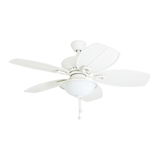
CEDAR SHOALS
1
ITEM #0726317, 0833274
CEILING FAN
MODEL #40045, 40156
Español p. 22
Advertisement
Table of Contents

Related Manuals for Harbor Breeze 40045

Summary of Contents for Harbor Breeze 40045
- Page 1 ITEM #0726317, 0833274 CEDAR SHOALS CEILING FAN MODEL #40045, 40156 Harbor Breeze® is a registered trademark Español p. 22 of LF, LLC. All Rights Reserved. ATTACH YOUR RECEIPT HERE Purchase Date _________________________ Questions, problems, missing parts? Before returning to your retailer, call our customer service department at 1-800-643-0067, 8 a.m.
-
Page 2: Table Of Contents
TABLE OF CONTENTS Package Contents ..............3 Hardware Contents . -
Page 3: Package Contents
PACKAGE CONTENTS PART DESCRIPTION QUANTITY Downrod Downrod Pin (preassembled to Downrod [A]) Downrod Clip (preassembled to Downrod [A]) Mounting Bracket (preassembled to Canopy [E]) Canopy Canopy Cover (preassembled to Canopy [E]) Motor Assembly Switch Housing Switch Housing Cap (preassembled to Light Kit [K]) Hood (preassembled to Light Kit [K]) Light Kit Finial Cap (preassembled to Light Kit [K]) -
Page 4: Hardware Contents
HARDWARE CONTENTS (shown actual size) Wire Connector Blade Screw Blade Washer Rubber Washer Pull Chain Extension Qty. 3 Qty. 15 Qty. 15 Qty. 15 Qty. 2 + 1 extra + 1 extra + 1 extra + 1 extra... -
Page 5: Safety Information
SAFETY INFORMATION Please read and understand this entire manual before attempting to assemble, operate or install the product. • Before you begin installing the fan, disconnect the power by removing fuses or turning off the circuit breakers. • Make sure all electrical connections comply with local codes, ordinances, the National Electrical Code and ANSI/NFPA 70-199. Hire a qualified electrician or consult a do-it-yourself wiring handbook if you are unfamiliar with installing electrical wiring. • Make sure the installation site you choose allows a minimum clearance of 7 ft. -
Page 6: Preparation
SAFETY INFORMATION CAUTION: Read all instructions and safety information before installing your new fan. Review the accompanying assembly diagrams. CAUTION: Be sure the outlet box is properly grounded or that a ground (green or bare) wire is present. CAUTION: Carefully check all screws, bolts and nuts on the fan motor assembly to ensure they are secured. -
Page 7: Initial Installation
INITIAL INSTALLATION 1. Turn off the circuit breakers and the wall switch to the fan supply line leads. DANGER: Failure to disconnect the power supply prior to installation may result in serious injury or death. 2. Determine the mounting method to use. Standard mounting is best suited for ceilings 8 ft. or higher. - Page 8 INITIAL INSTALLATION 4. Loosen all four preassembled mounting bracket screws (U), then completely remove the two mounting bracket screws (U) from the round holes of canopy (E). Set aside for later use. Detach mounting bracket (D) from canopy (E). 5. Attach mounting bracket (D) to outlet box (not Standard or included) using screws and washers provided with Closemount...
-
Page 9: Standard Or Angle Mounting Instructions
STANDARD OR ANGLE MOUNTING INSTRUCTIONS 1. Remove the downrod pin (B) and downrod clip (C) from the downrod (A). Then partially loosen the set screws (Y) in the yoke at the top of the motor assembly (G). Yoke 2. Insert the downrod (A) through the canopy (E) and yoke cover (N). - Page 10 STANDARD OR ANGLE MOUNTING INSTRUCTIONS 4. Depending on the length of downrod you use, you may need to cut the lead wires back to simplify the wiring. If you decide to cut back the lead wires, take the lead wires and make sure you have pulled them all the way 8 in.
-
Page 11: Closemount Instructions
CLOSEMOUNT INSTRUCTIONS Helpful Hint: The downrod (A), canopy cover (F) and yoke cover (N) are not used in this type of installation. 1. Remove and discard the canopy cover (F) from the bottom of the canopy (E). 2. Remove three Phillips-head closemount screws (X) from the top of the motor assembly (G). -
Page 12: Wiring
WIRING WARNING: To reduce the risk of fire, electrical shock or personal injury, wire connectors provided with this fan are designed to accept only one 12-gauge house wire and two lead wires from the fan. If your house wire is larger than 12-gauge and there is more than one house wire to connect to the two fan lead wires, consult an electrician for the proper size wire connectors to use. -
Page 13: Final Installation
FINAL INSTALLATION Note: Closemount installation will not have the downrod (A), yoke cover (N) or canopy cover (F). 1. Align the canopy (E) over the loosened mounting bracket screws (U) preassembled on mounting bracket (D). Place the keyholes of the canopy (E) onto the mounting bracket screws (U) and rotate the canopy (E) clockwise. - Page 14 FINAL INSTALLATION 4. Install the blade arm (R) to the underside of the motor assembly (G) with motor screws (T) previously removed (Step 6, page 8). Tighten with Phillips screwdriver. Repeat for each blade arm (R). 5. Remove one of the adapter plate screws (AC) from the adapter plate (AB), and loosen (do not remove) the other two screws.
- Page 15 FINAL INSTALLATION 7. Remove the three switch housing screws (Z) from the switch housing cap (I). Then connect the single-pin connector from the switch housing (H) to the single- pin connector from the light kit (K) -- Blue to Black and White to White.
- Page 16 FINAL INSTALLATION 10. Attach the pull chain extensions (EE) or custom pull chain extensions (not included) to the fan and light pull chains. Proceed to Step 12. Hardware Used Fan Pull Chain Pull Chain Light Pull Chain Extension 11. To install the fan without the light kit (K), remove the three switch housing screws (Z) from the switch housing cap (I).
-
Page 17: Operating Instructions
OPERATING INSTRUCTIONS 1. The fan pull chain has four positions to control the fan speed. One pull is HIGH, two is MEDIUM, three is LOW, and four turns the fan OFF. The pull chain in the center of the light kit (G), if applicable, turns the lights ON and OFF. -
Page 18: Care And Maintenance
CARE AND MAINTENANCE At least twice each year, lower the canopy to check the downrod assembly, and then tighten all screws on the fan. Clean the motor assembly with only a soft brush or lint-free cloth to avoid scratching the finish. Clean the blades with a lint-free cloth. Bulb Replacement: Use 60-watt max. E26-base LED, CFL or incandescent bulbs. Halogen bulbs are not recommended for this item. - Page 19 TROUBLESHOOTING PROBLEM POSSIBLE CAUSE CORRECTIVE ACTION 1. The blades and/or blade arms 1. Check and tighten all screws that hold are loose. the fan blades to the blade arms and the blade arms to the motor. 2. The blades are unbalanced. 2.
-
Page 20: Limited Lifetime Warranty
LIFETIME LIMITED WARRANTY The manufacturer warrants this fan to be free from defects in workmanship and materials present at time of shipment from the factory for a lifetime from the date of purchase by the original purchaser. The retailer also warrants that all other fan parts, excluding any glass or plastic blades, to be free from defects in workmanship and material at the time of shipment from the factory for a period of one year after the date of purchase by the original purchaser. -
Page 21: Replacement Parts List
REPLACEMENT PARTS LIST For replacement parts, call the customer service department at 1-800-643-0067, 8 a.m. - 6 p.m., EST, Monday - Thursday, 8 a.m. - 5 p.m., EST, Friday. PART DESCRIPTION 0726317 0833274 PART # PART # Downrod 0726317-A 0833274-A Mounting Bracket 0726317-D 0833274-D...
Need help?
Do you have a question about the 40045 and is the answer not in the manual?
Questions and answers