Table of Contents
Advertisement
Available languages
Available languages
Harbor Breeze® is a registered trademark
of LF, LLC. All Rights Reserved.
ATTACH YOUR RECEIPT HERE
Serial Number
Questions, problems, missing parts? Before returning to your retailer, call our customer
service department at 1-800-643-0067, 8 a.m. - 6 p.m., EST, Monday - Thursday and
8 a.m. - 5 p.m., EST, Friday.
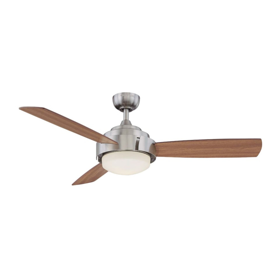
ELEVATION CEILING FAN
Purchase Date
ITEM #0072028
MODEL #LP8071LBN
Español p. 21
Advertisement
Chapters
Table of Contents

Subscribe to Our Youtube Channel
Related Manuals for Harbor Breeze LP8071LBN

Summary of Contents for Harbor Breeze LP8071LBN
- Page 1 ITEM #0072028 ELEVATION CEILING FAN MODEL #LP8071LBN Harbor Breeze® is a registered trademark of LF, LLC. All Rights Reserved. Español p. 21 ATTACH YOUR RECEIPT HERE Serial Number Purchase Date Questions, problems, missing parts? Before returning to your retailer, call our customer service department at 1-800-643-0067, 8 a.m.
-
Page 2: Table Of Contents
TABLE OF CONTENTS Safety Information ......................... Package Contents ......................... Hardware Contents ........................Preparation ........................... Assembly Instructions ........................Hanging Instructions ........................Wiring Instructions ........................Canopy Housing Installation ......................Blade Installation .......................... Light Fitter Assembly Installation ....................Fan Operating Instructions ......................Blade Balancing Installation Instructions ..................Care and Maintenance ......................... -
Page 3: Safety Information
SAFETY INFORMATION Please read and understand this entire manual before attempting to assemble, operate or install the product. If you have any questions regarding the product, please call customer service at 1-800-643-0067, 8 a.m. - 6 p.m., EST, Monday - Thursday and 8 a.m. - 5 p.m., EST, Friday. •... - Page 4 SAFETY INFORMATION (Continued) WARNING This fan is to be used in dry locations only. •The net weight of this fan is: 21.08 lbs. (9.56 kg).
-
Page 5: Package Contents
PACKAGE CONTENTS PART DESCRIPTION QUANTITY PART DESCRIPTION QUANTITY Motor Assembly Blade Hanger Bracket Remote Hanger Ball / Downrod Assembly Ceiling Canopy Canopy Screw Cover Motor Coupling Cover Light Fitter Assembly Socket Plate Assembly Glass Bulb... -
Page 6: Hardware Contents
HARDWARE CONTENTS (shown actual size) Fiber Washer-Head Washers Wire Screws Connectors Qty. 10 Qty. 10 Qty. 3 Balance (not shown to size) Qty. 1 PREPARATION Before beginning assembly of product, make sure all parts are present. Compare parts with. package contents list and diagram above. If any part is missing or damaged, do not attempt to assemble the product. -
Page 7: Assembly Instructions
ASSEMBLY INSTRUCTIONS 1. Remove the hanger ball portion from the downrod/hanger ball assembly (C) by loosen- ing the set screw in the hanger ball until the ball falls freely down the downrod. Remove the pin from the downrod, then remove the hanger ball. - Page 8 ASSEMBLY INSTRUCTIONS (Continued) 4. Remove the two screws in the motor assembly (A). Retain the two screws for inatallation in step 5. (Fig. 4) 5. Route wires through motor coupling cover (F) and tight the two screws from the motor assembly (A).
- Page 9 ASSEMBLY INSTRUCTIONS (Continued) 7. Reinstall the hanger ball on the downrod/hanger ball assembly (C) by routing the three 54 in. wires through the hanger ball. Position the pin from the downrod/hanger ball assembly (C) through the two holes in the downrod and align the hanger ball so the pin is captured in the groove in the top of the hanger ball.
-
Page 10: Hanging Instructions
HANGING INSTRUCTIONS (Continued) 1. Securely attach the hanger bracket (B) to the outlet box using the outlet box screws and washers supplied with the outlet box (not included). (Fig. 1) WARNING The outlet box must be securely anchored. Hanger bracket must seat firmly against outlet box. -
Page 11: Wiring Instructions
WIRING INSTRUCTIONS WARNING To avoid possible electrical shock, be sure electricity is turned off at the main fuse box before hanging. NOTE: If you are not sure if the outlet box is grounded, contact a licensed electrician for advice, as it must be grounded for safe operation. -
Page 12: Canopy Housing Installation
CANOPY HOUSING INSTALLATION 1. Remove one of the two shoulder screws in the hanger bracket (B). Loosen the second shoulder screw without fully removing it. Assemble ceiling canopy (D) by rotating key slot over shoulder screw in hanger bracket (B). Tighten shoulder screw. -
Page 13: Light Fitter Assembly Installation
LIGHT FITTER ASSEMBLY INSTALLATION 1. Remove one of the three screws in the adapter plate at the bottom of the motor assembly (A). Slightly loosen the remaining two screws. Assemble the light fitter assembly (G) to the adapter plate of motor assembly (A) using the two key slots in the light fitter assembly (G). -
Page 14: Fan Operating Instructions
LIGHT FITTER ASSEMBLY INSTALLATION (Continued) 4. Install bulb (J). (Fig. 4) CAUTION Bulb is pressurized and may shatter. DO NOT TOUCH BULB WITH BARE HANDS. Fingerprints may result in shorter bulb life. Remove fingerprints with alcohol prior to use. To reduce the risk of fire, use 100-watt max. type T4-minican JD E11 tungsten halogen bulb. - Page 15 FAN OPERATING INSTRUCTIONS (Continued) 2. After installing the unit and restoring power to your fan, open the battery cover (with battery, DC12V/A23, installed) and press and hold the “learning button” 1~3 seconds with a ball-point pen or similar object. Fan will turn off and then turn to medium speed, which indicates that the learning process has completed.
-
Page 16: Blade Balancing Installation Instructions
BLADE BALANCING INSTALLATION INSTRUCTIONS WARNING The balancing clip must always be firmly pushed onto the blade till it touches the edge of the blade. Failure to do so could allow clip to fly off and cause personal injury. 1. Interchanging positions of adjacent blades (K) can redistribute the weight and result in a smoother operation. -
Page 17: Care And Maintenance
CARE AND MAINTENANCE •When cleaning, use only a soft brush or lint-free cloth to avoid scratching the finish. •Abrasive cleaning agents are not required and should be avoided to prevent damage to finish. WARNING Do not use water when cleaning your ceiling fan. It could damage the motor or the finish and create the possibility of electrical shock. - Page 18 TROUBLESHOOTING (Continued) PROBLEM POSSIBLE CAUSE CORRECTIVE ACTION Fan sounds 4. Wire connectors inside 4. Check to make sure wire connectors in housing rattling. switch housing are not rattling against noisy each other or against the interior wall of the switch housing. WARNING Make sure main power is turned off! 5.
-
Page 19: Warranty
WARRANTY The manufacturer warrants this fan to be free from defects in workmanship and material present at time of shipment from the factory for life (with limitations) from the date of purchase. This warranty applies only to the original purchaser. The manufacturer agrees to correct such defect at no change or at our option replace the ceiling fan with a comparable or superior model. -
Page 20: Replacement Parts List
REPLACEMENT PARTS LIST For replacement parts, call our customer service department at 1-800-643-0067, 8 a.m.-6 p.m., EST, Monday-Thursday and 8 a.m.-5 p.m., EST, Friday. Motor Assembly AMA8071LBN Hanger Bracket (with Screws) APGAC110RBL Hanger Ball/Downrod Assembly ADRACT1-45LBN Ceiling Canopy P801301LBN Canopy Screw Cover APPAC1101LBN Motor Coupling Cover AP807101LBN... - Page 21 ARTÍCULO #0072028 VENTILADOR DE TECHO ELEVATION MODELO #LP8071LBN Harbor Breeze® es una marca registrada de LF, LLC. Todos los derechos reservados. Adjuntar su recibo AQUÍ Número de serie Fecha de Compra ¿Preguntas, problemas, piezas faltantes? Antes de volver a la tienda, llame a nuestro Departamento de Servicio al Cliente al 1-800-643-0067, de lunes a jueves de 8 a.m.
- Page 22 ÍNDICE Información de seguridad ......................Contenido del paquete ......................... Aditamentos ..........................Preparación ..........................Instrucciones de ensamblaje ......................Instrucciones para colgar ......................Instrucciones de cableado ......................Instalación de la carcasa de la base .................... Instalación de las aspas ....................... Instalación del ensamble del soporte de iluminación ..............
-
Page 23: Información De Seguridad
INFORMACIÓN DE SEGURIDAD Lea y comprenda completamente este manual antes de intentar ensamblar, usar o instalar el producto. Si tiene preguntas relacionadas con el producto, llame a nuestro Departamento de Servicio al Cliente al 1-800-643-0067, de lunes a jueves de 8 a.m. a 6 p.m. y los viernes de 8 a.m. - Page 24 INFORMACIÓN DE SEGURIDAD (Continuación) ADVERTENCIA Para reducir el riesgo de incendios, descargas eléctricas o lesiones personales, no doble los brazos de las aspas al instalarlas, al equilibrarlas o al limpiar el ventilador. No introduzca objetos extraños entre las aspas en movimiento. Instale en una caja de salida marcada como “ACCEPTABLE FOR FAN SUPPORT”...
-
Page 25: Contenido Del Paquete
CONTENIDO DEL PAQUETE PIEZA DESCRIPCIÓN CANTIDAD PIEZA DESCRIPCIÓN CANTIDAD Ensamble del motor Aspa L Control remoto de mano Abrazadera para colgar Ensamble de la bola para colgar/varilla Escudo del techo Cubierta para los tornillo de la base Cubierta para el acoplador del motor Ensamble del soporte de iluminación Ensamble de la placa del portalámpara Vidrio... -
Page 26: Aditamentos
ADITAMENTOS (Se muestan en tamaño real) Arandelas Tornillos con de fibra Conectores cabeza de de cable arandela Cant. 10 Cant. 3 Cant. 10 Kit de equilibrio (no se muestra en tamaño real) Cant. 1 PREPARACIÓN Antes de comenzar a ensamblar el producto, asegúrese de tener todas las piezas. Compare las piezas con la lista del contenido del paquete y el diagrama anterior. -
Page 27: Instrucciones De Ensamblaje
INSTRUCCIONES DE ENSAMBLAJE 1. Retire la parte correspondiente a la bola para colgar del ensamble de la bola para colgar/varilla(C) aflojando el tornillo de fijación de la bola hasta que ésta salga libremente de la varilla. Retire el pasador de la varilla y luego retire la bola para colgar. - Page 28 INSTRUCCIONES DE ENSAMBLAJE (Continuación) 4. Retire los dos tornillos en el ensamble del motor (A). Guarde los dos tornillos para la instalación en el paso 5. (Fig. 4) 5. Pase los conductores a través de la cubierta del acoplador del motor (F) y apriete los dos tornillos del ensamble del motor (A).
-
Page 29: Instrucciones Para Colgar
INSTRUCCIONES DE ENSAMBLAJE (Continuación) 5. Vuelva a instalar la bola para colgar en el ensamble de la bola para colgar/varilla (C) haciendo pasar los tres conductores de 1,37 m a través de la bola para colgar. Coloque el pasador del ensamble de la bola para colgar/varilla (C) a través de los dos orificios de la varilla y alinee la bola para colgar de manera tal que el pasador quede inserto en la... - Page 30 INSTRUCCIONES PARA COLGAR (Continuación) ADVERTENCIA Debe colgar el ventilador a una distancia mínima de 2,13 m desde las aspas hasta el piso. 1. Fije bien la abrazadera para colgar (B) a la caja de salida con los tornillos y las arandelas provistas con la caja de salida (No se incluye).
-
Page 31: Instrucciones De Cableado
INSTRUCCIONES DE CABLEADO ADVERTENCIA Para evitar una posible descarga eléctrica,asegúrese de cortar la alimentación eléctrica de la caja de fusibles principal antes de colgar el ventilador. NOTA: Si no está seguro de si la caja de salida tiene conexión a tierra, pida consejo a un electricista certificado, ya que debe tener conexión a tierra para un funcionamiento seguro. -
Page 32: Instalación De La Carcasa De La Base
INSTALACIÓN DE LA CARCASA DE LA BASE 1. Retire uno de los dos tornillos de reborde de la abrazadera para colgar. Afloje el segundo tornillo de reborde sin retirarlo del todo. Ensamble la base de techo (D) girando el chavetero de la base (E) sobre el tornillo de reborde de la abrazadera para colgar (B). -
Page 33: Instalación Del Ensamble Del Soporte De Iluminación
INSTALACIÓN DEL ENSAMBLE DEL SOPORTE DE ILUMINACIÓN 1. Retire uno de los tres tornillos en la placa del adaptador en la parte inferior del ensamble del motor (A). Afloje ligeramente los dos tornillos restantes. Ensamble el ensamble del soporte de iluminación (G) en la placa del adaptador del ensamble de motor (A) mediante los dos chaveteros del ensamble del soporte de iluminación (G). -
Page 34: Instrucciones De Funcionamiento De La Cadena Del Tirador
INSTALACIÓN DEL ENSAMBLE DEL SOPORTE DE ILUMINACIÓN (Continuación) 4. Instale la bombilla (J). (Fig. 4) PRECAUCIÓN La bombilla está presurizada y puede quebrarse. NO TOQUE LA BOMBILLA CON LAS MANOS DESPROTEGIDAS. Las huellas dactilares en la bombilla pueden reducir la vida útil de la misma. Elimine las huellas dactilares con alcohol antes de usar la bombilla. - Page 35 INSTRUCCIONES DE FUNCIONAMIENTO DEL VENTILADOR (Continuación) 2. Después de instalar la unidad y de reestablecer la alimentación al ventilador, abra la cubierta de la batería (con batería CC 12 V/A23 instalada) y mantenga presionado el "botón de aprendizaje" entre 1 y 3 segundos con un bolígrafo u objeto similar.
-
Page 36: Instrucciones De Instalación De Aspa Equilibrada
INSTRUCCIONES DE INSTALACIÓN DE ASPA EQUILIBRADA ADVERTENCIA El sujetador de equilibrio siempre se debe empujar firmemente en el aspa hasta que toque el borde de ésta. Si no lo hace, el sujetador puede salir disparado y causar daños personales. 1. Intercambiar la posición de aspas adyacentes (K) puede redistribuir el peso y hacer que funcione más suavemente. -
Page 37: Cuidado Y Mantenimiento
CUIDADO Y MANTENIMIENTO •El único mantenimiento que necesita el ventilador de techo es la limpieza periódica. Use sólo una brocha suave o un paño sin pelusa para evitar rayar el acabado al limpiar. Los agentes limpiadores abrasivos son innecesarios y deben evitarse para no dañar el acabado. ADVERTENCIA No use agua para limpiar el ventilador de techo. - Page 38 SOLUCIÓN DE PROBLEMAS (Continuación) PROBLEMA CAUSA POSIBLE ACCIÓN CORRECTIVA El ventilador 4. Los conectores de cable de la 4. Compruebe que los conectores de carcasa repiquetean. cable de la carcasa del interruptor no emite mucho repiqueteen unos contra otros o contra ruido las paredes interiores de la carcasa del (Continuación)
-
Page 39: Garantía
GARANTÍA El fabricante garantiza, de por vida, (con limitaciones) que este ventilador no presenta defectos ni de fabricación ni en los materiales presentes en el momento del transporte desde la fábrica a partir de la fecha de compra. Esta garantía es válida sólo para el comprador original. El fabricante acepta reparar dichos defectos sin cargo o, según nuestro criterio, reemplazar el ventilador de techo por un modelo comparable o superior. -
Page 40: Lista De Piezas De Repuesto
LISTA DE PIEZAS DE REPUESTO Para obtener piezas de repuesto, llame a nuestro Departamento de Servicio al Cliente al 1-800-643- 0067, de lunes a jueves de 8 a.m. a 6 p.m. y los viernes de 8 a.m. a 5 p.m., hora estándar del Este. Ó...
Need help?
Do you have a question about the LP8071LBN and is the answer not in the manual?
Questions and answers