Cisco Catalyst 2960-L Smart Managed Series Hardware Installation Manual

Cisco Catalyst 2960-L Smart Managed Series Hardware Installation Manual

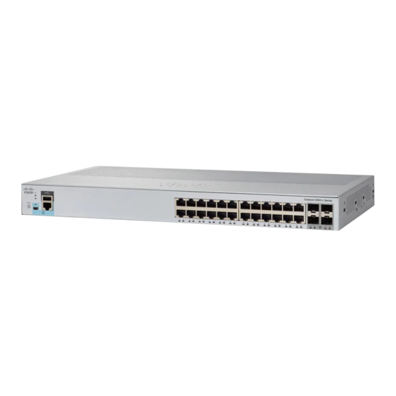
Smart managed 24-portand 48-port switch
Hide thumbs Also See for Catalyst 2960-L Smart Managed Series:
Table of Contents

Advertisement

Quick Links

Cisco Catalyst 2960-L Smart Managed Series 24-Port and 48-Port Switch
Hardware Installation Guide
First Published: 2018-11-30
Americas Headquarters
Cisco Systems, Inc.
170 West Tasman Drive
San Jose, CA 95134-1706
USA
http://www.cisco.com
Tel: 408 526-4000
800 553-NETS (6387)
Fax: 408 527-0883

Advertisement

Table of Contents
loading

Summary of Contents for Cisco Catalyst 2960-L Smart Managed Series

  • Page 1 Cisco Catalyst 2960-L Smart Managed Series 24-Port and 48-Port Switch Hardware Installation Guide First Published: 2018-11-30 Americas Headquarters Cisco Systems, Inc. 170 West Tasman Drive San Jose, CA 95134-1706 http://www.cisco.com Tel: 408 526-4000 800 553-NETS (6387) Fax: 408 527-0883...
  • Page 2: Table Of Contents

    PoE LED Console LEDs Port LEDs Rear Panel Internal Power Supply Security Slot Network Configurations C H A P T E R 2 Switch Installation Safety Warnings Cisco Catalyst 2960-L Smart Managed Series 24-Port and 48-Port Switch Hardware Installation Guide...
  • Page 3 Troubleshooting Diagnosing Problems Switch POST Results Switch LEDs Switch Connections Bad or Damaged Cable Ethernet and Fiber-Optic Cables Link Status 10/100/1000 Port Connections 10/100/1000 PoE+ Port Connections Cisco Catalyst 2960-L Smart Managed Series 24-Port and 48-Port Switch Hardware Installation Guide...
  • Page 4 Accessing the CLI Through the Console Port Connecting the RJ-45 Console Port Connecting the USB Console Port Installing the Cisco Microsoft Windows USB Device Driver Installing the Cisco Microsoft Windows XP USB Driver Cisco Catalyst 2960-L Smart Managed Series 24-Port and 48-Port Switch Hardware Installation Guide...
  • Page 5 Uninstalling the Cisco Microsoft Windows USB Driver Uninstalling the Cisco Microsoft Windows XP and 2000 USB Driver Uninstalling the Cisco Microsoft Windows Vista and Windows 7 USB Driver Cisco Catalyst 2960-L Smart Managed Series 24-Port and 48-Port Switch Hardware Installation Guide...
  • Page 6 Contents Cisco Catalyst 2960-L Smart Managed Series 24-Port and 48-Port Switch Hardware Installation Guide...
  • Page 7 Cisco has more than 200 offices worldwide. Addresses and phone numbers are listed on the Cisco website at www.cisco.com/go/offices. Cisco and the Cisco logo are trademarks or registered trademarks of Cisco and/or its affiliates in the U.S. and other countries. To view a list of Cisco trademarks, go to this URL: www.cisco.com...
  • Page 9: Preface

    Optional alternative keywords are grouped in brackets and separated by vertical bars. {x | y} Required alternative keywords are grouped in braces and separated by vertical bars. Cisco Catalyst 2960-L Smart Managed Series 24-Port and 48-Port Switch Hardware Installation Guide...
  • Page 10 Use the statement number provided at the end of each warning to locate its translation in the translated safety warnings that accompanied this device. Statement 1071 SAVE THESE INSTRUCTIONS Cisco Catalyst 2960-L Smart Managed Series 24-Port and 48-Port Switch Hardware Installation Guide...
  • Page 11: Obtaining Documentation And Submitting A Service Request

    Obtaining Documentation and Submitting a Service Request For information on obtaining documentation, submitting a service request, and gathering additional information, see the monthly What's New in Cisco Product Documentation, which also lists all new and revised Cisco technical documentation, at: http://www.cisco.com/c/en/us/td/docs/general/whatsnew/whatsnew.html...
  • Page 12 Preface Obtaining Documentation and Submitting a Service Request Cisco Catalyst 2960-L Smart Managed Series 24-Port and 48-Port Switch Hardware Installation Guide...
  • Page 13: Product Overview

    C H A P T E R Product Overview The Cisco Catalyst 2960-L Smart Managed Series switches are fixed-configuration, Gigabit Ethernet switches that provide entry-level enterprise-class Layer 2 access for branch offices, conventional workspace, and out-of-wiring closet applications. Cisco Catalyst 2960-L Smart Managed Series switches provide support for the following features: •...
  • Page 14: Front Panel

    370W); four 10-Gigabit Ethernet small form-factor pluggable plus (SFP+) module uplink slots Front Panel This section describes the front panel components of a 24-port and 48-port Cisco Catalyst 2960-L Smart Managed switch. • 24 or 48 downlink ports of one of these types: •...
  • Page 15 Product Overview Front Panel Figure 1: Front Panel of a 24-Port Cisco Catalyst 2960-L Smart Managed PoE Switch Mode button USB mini-Type B (console) port Switch LEDs RJ-45 console port USB Type A port SFP module slots 24 10/100/1000 PoE+...
  • Page 16: Poe Ports

    • USB mini-Type B console port (5-pin connector). If you use the USB mini-Type B console port, the Cisco Windows USB device driver must be installed on any PC connected to the console port (for operation with Microsoft Windows). Mac OS X or Linux do not require special drivers.
  • Page 17: Usb Type A Port

    The port supports Cisco USB flash drives with capacities from 128 MB to 8 GB (USB devices with port densities of 128 MB, 256 MB, 1 GB, 4 GB, and 8 GB are supported). Cisco IOS software provides standard file system access to the flash device: read, write, erase, and copy, as well as the ability to format the flash device with a FAT file system.
  • Page 18: Leds

    1-GigabitEthernet ports 10-GigabitEthernet ports GigabitEthernet0/49 TenGigabitEthernet0/1 GigabitEthernet0/50 TenGigabitEthernet0/2 GigabitEthernet0/51 TenGigabitEthernet0/3 GigabitEthernet0/52 TenGigabitEthernet0/4 LEDs You can use the switch system and port LEDs to monitor switch activity and performance. Cisco Catalyst 2960-L Smart Managed Series 24-Port and 48-Port Switch Hardware Installation Guide...
  • Page 19: System Led

    System Status System is not powered on. Green System is operating normally. Amber System is receiving power but is not operating properly. Blinking Green POST is in progress. Cisco Catalyst 2960-L Smart Managed Series 24-Port and 48-Port Switch Hardware Installation Guide...
  • Page 20: Modes For Port Leds

    RJ-45 ports and SFP-module slots have port LEDs. These LEDs, as a group or individually, provide information about the switch and about the individual ports. LED Color Description No link or port was administratively shut down. Cisco Catalyst 2960-L Smart Managed Series 24-Port and 48-Port Switch Hardware Installation Guide...
  • Page 21: Rear Panel

    • Heat sink fins (PoE models only) Figure 5: Rear Panel of a Non-PoE Switch Security Slot A loop (for the optional power cord retainer) An AC power connector Cisco Catalyst 2960-L Smart Managed Series 24-Port and 48-Port Switch Hardware Installation Guide...
  • Page 22: Internal Power Supply

    The switches have security slots on the rear panel. You can install an optional cable lock, such as the type that is used to secure a laptop computer, to secure the switch. Cisco Catalyst 2960-L Smart Managed Series 24-Port and 48-Port Switch Hardware Installation Guide...
  • Page 23: Network Configurations

    See the switch software configuration guide for network configuration concepts and examples of using the switch to create dedicated network segments and interconnecting the segments through Fast Ethernet and Gigabit Ethernet connections. Cisco Catalyst 2960-L Smart Managed Series 24-Port and 48-Port Switch Hardware Installation Guide...
  • Page 24 Product Overview Network Configurations Cisco Catalyst 2960-L Smart Managed Series 24-Port and 48-Port Switch Hardware Installation Guide...
  • Page 25: Switch Installation

    Statement 43 Warning Do not stack the chassis on any other equipment. If the chassis falls, it can cause severe bodily injury and equipment damage. Statement 48 Cisco Catalyst 2960-L Smart Managed Series 24-Port and 48-Port Switch Hardware Installation Guide...
  • Page 26 This equipment must be grounded. Never defeat the ground conductor or operate the equipment in the absence of a suitably installed ground conductor. Contact the appropriate electrical inspection authority or an electrician if you are uncertain that suitable grounding is available. Statement 1024 Cisco Catalyst 2960-L Smart Managed Series 24-Port and 48-Port Switch Hardware Installation Guide...
  • Page 27 Statement 1072 Warning No user-serviceable parts inside. Do not open. Statement 1073 Cisco Catalyst 2960-L Smart Managed Series 24-Port and 48-Port Switch Hardware Installation Guide...
  • Page 28: Box Contents

    Hot surface. Statement 1079 Box Contents This section lists the contents of the shipping box for a 24-port and 48-port Cisco Catalyst 2960-L Smart Managed switch. Figure 8: Box Contents of a 24-Port and 48-Port Cisco Catalyst 2960-L Smart Managed Switch...
  • Page 29: Tools And Equipment

    • Altitude at the installation site is not greater than 10,000 feet. • For 10/100/1000 fixed ports, the cable length from a switch to a connected device cannot exceed 328 feet (100 meters). Cisco Catalyst 2960-L Smart Managed Series 24-Port and 48-Port Switch Hardware Installation Guide...
  • Page 30: Verifying Switch Operation

    If a switch fails POST, the SYST LED turns amber. POST failures are usually fatal. Call Cisco technical support representative if your switch fails POST. After a successful POST, unplug the power cord from the switch and install the switch in a rack, on a wall, on a table, or on a shelf.
  • Page 31: Attaching The Rack-Mount Brackets

    24-inch brackets Attaching the Rack-Mount Brackets Attaching the Rack-Mount Brackets to a 24-Port and 48-Port Cisco Catalyst 2960-L Smart Managed Switch Use two Phillips flat-head screws to attach the long side of the bracket to each side of the switch.
  • Page 32 Switch Installation Attaching the Rack-Mount Brackets Figure 10: Attaching 19-inch Brackets to a 24-Port and 48-Port Cisco Catalyst 2960-L Smart Managed Switch Cisco Catalyst 2960-L Smart Managed Series 24-Port and 48-Port Switch Hardware Installation Guide...
  • Page 33: Mounting A 24-Port Or 48-Port Switch In A Rack

    Figure 11: Mounting the Switch in a Rack Cable guide Number-12 Phillips pan-head screws (48-0523-01) or Number-10 Phillips pan-head screws (48-0627-01) Phillips machine screw, black (48-0654-01) Mid-mounting position Cisco Catalyst 2960-L Smart Managed Series 24-Port and 48-Port Switch Hardware Installation Guide...
  • Page 34: Wall-Mounting

    Step 2 Follow the same steps to attach the second bracket to the opposite side. Figure 12: Attaching the 19-inch Brackets for Wall-Mounting Number-8 phillips flat-head screws (48-2927-01) Cisco Catalyst 2960-L Smart Managed Series 24-Port and 48-Port Switch Hardware Installation Guide...
  • Page 35: Mounting On A Wall

    1. To install the switch on a table or shelf, locate the adhesive strip with the rubber feet in the mounting-kit envelope. 2. Attach the four rubber feet to the four circular etches on the bottom of the chassis. Cisco Catalyst 2960-L Smart Managed Series 24-Port and 48-Port Switch Hardware Installation Guide...
  • Page 36: After Switch Installation

    Choose the sleeve size of the power cord retainer based on the thickness of the cord. The smaller sleeve can be snapped off and used for thin cords. Step 2 Slide the retainer around the AC power cord, and pass it around the loop on the switch. Cisco Catalyst 2960-L Smart Managed Series 24-Port and 48-Port Switch Hardware Installation Guide...
  • Page 37 Figure 15: Sliding the Retainer Through the Latch AC power cord Latch Smaller sleeve for thin power cords Step 4 Slide the retainer through the other latches to lock it. Cisco Catalyst 2960-L Smart Managed Series 24-Port and 48-Port Switch Hardware Installation Guide...
  • Page 38 Figure 17: Sleeve Around the Power Cord Sleeve for thin power cords AC power cord Step 6 Secure the AC power cord by pressing on the retainer. Cisco Catalyst 2960-L Smart Managed Series 24-Port and 48-Port Switch Hardware Installation Guide...
  • Page 39: Installing Sfp Modules

    Attach an ESD-preventive wrist strap to your wrist and to a bare metal surface. Step 2 Find the send (TX) and receive (RX) markings on the module top. Cisco Catalyst 2960-L Smart Managed Series 24-Port and 48-Port Switch Hardware Installation Guide...
  • Page 40: Removing An Sfp Or Sfp+ Module

    Place the module in an antistatic bag or other protective environment. Connecting to SFP or SFP+ Modules Connecting to Fiber-Optic SFP or SFP+ Modules Warning Class 1 laser product. Statement 1008 Cisco Catalyst 2960-L Smart Managed Series 24-Port and 48-Port Switch Hardware Installation Guide...
  • Page 41 The LED turns amber while the STP discovers the network topology and searches for loops. This process takes about 30 seconds, and then the port LED turns green. Cisco Catalyst 2960-L Smart Managed Series 24-Port and 48-Port Switch Hardware Installation Guide...
  • Page 42: Connecting To 1000Base-T Sfp

    Insert a four twisted-pair, crossover cable when you connect to switches or repeaters. Step 2 Connect the other end of the cable to an RJ-45 connector on the other device. Cisco Catalyst 2960-L Smart Managed Series 24-Port and 48-Port Switch Hardware Installation Guide...
  • Page 43: 10/100/1000 Poe And Poe+Port Connections

    Cisco prestandard PoE support for Cisco IP Phones and Cisco Aironet Access Points. On a per-port basis, you can control whether or not a port automatically provides power when an IP phone or an access point is connected. Cisco Catalyst 2960-L Smart Managed Series 24-Port and 48-Port Switch Hardware Installation Guide...
  • Page 44 Switch Installation 10/100/1000 PoE and PoE+Port Connections To access an advanced PoE planning tool, use the Cisco Power Calculator available on Cisco.com at this URL: http://tools.cisco.com/cpc/launch.jsp You can use this application to calculate the power supply requirements for a specific PoE configuration. The results show output current, output power, and system heat dissipation.
  • Page 45: 10/100/1000 Port Connections

    Switch Installation 10/100/1000 Port Connections Many legacy powered devices, including older Cisco IP phones and access points that do not fully support Note IEEE 802.3af, might not support PoE when connected to the switches by a crossover cable. 10/100/1000 Port Connections The switch 10/100/1000 port configuration changes to operate at the speed of the attached device.
  • Page 46 Switch Installation Auto-MDIX Connections Cisco Catalyst 2960-L Smart Managed Series 24-Port and 48-Port Switch Hardware Installation Guide...
  • Page 47: Troubleshooting

    You can also get statistics from Device Manager, from the CLI, or from an SNMP workstation. Switch POST Results POST failures are usually fatal. Contact your Cisco technical support representative if your switch does not pass POST. Switch LEDs If you have physical access to the switch, look at the port LEDs for troubleshooting information about the switch.
  • Page 48: Ethernet And Fiber-Optic Cables

    • Use the show interfaces privileged EXEC command to see if the port is in error-disabled, disabled, or shutdown. Reenable the port if necessary. • Verify that the power supply installed in the switch meets the power requirements of your connected devices. Cisco Catalyst 2960-L Smart Managed Series 24-Port and 48-Port Switch Hardware Installation Guide...
  • Page 49: Sfp And Sfp+ Module

    SFP and SFP+ Module Use only Cisco SFP or SFP+ modules in the switch. Each Cisco module has an internal serial EEPROM that is encoded with security information. This encoding provides a way for Cisco to identify and validate that the module meets the requirements for the switch.
  • Page 50: Switch Performance

    Finding the Switch Serial Number If you contact Cisco Technical Assistance, you need to know the switch serial number. You can also use the show version privileged EXEC command to see the switch serial number.
  • Page 51 Troubleshooting Finding the Switch Serial Number Figure 22: Serial Number Location MAC address PID number CLEI code Serial number Cisco Catalyst 2960-L Smart Managed Series 24-Port and 48-Port Switch Hardware Installation Guide...
  • Page 52 Troubleshooting Finding the Switch Serial Number Cisco Catalyst 2960-L Smart Managed Series 24-Port and 48-Port Switch Hardware Installation Guide...
  • Page 53: Technical Specifications

    • 6.06 lbs (2.75 kg) (Cisco Catalyst 2960L-SM-24TQ) • 7.39 lbs (3.35 kg) (Cisco Catalyst 2960L-SM-24PQ) • 6.68 lbs (3.03 kg) (Cisco Catalyst 2960L-SM-48TQ) • 10.01 lbs (4.54 kg) (Cisco Catalyst 2960L-SM-48PQ) Cisco Catalyst 2960-L Smart Managed Series 24-Port and 48-Port Switch Hardware Installation Guide...
  • Page 54: Environmental Specifications

    Technical Specifications Environmental Specifications Dimensions (H x D x W) • 1.73 x 9.45 x 17.5 in. (4.4 x 24 x 44.5 cm) (Cisco Catalyst 2960L-SM-24TS) • 1.73 x 10.45 x 17.5 in. (4.4 x 26.5 x 44.5 cm) (Cisco Catalyst 2960L-SM-24PS) •...
  • Page 55: Power Requirements

    • 0.48 KVA (Cisco Catalyst 2960L-SM-48PS) • 0.06 KVA (Cisco Catalyst 2960L-SM-24TQ) • 0.24 KVA (Cisco Catalyst 2960L-SM-24PQ) • 0.09 KVA (Cisco Catalyst 2960L-SM-48TQ) • 0.48 KVA (Cisco Catalyst 2960L-SM-48PQ) Cisco Catalyst 2960-L Smart Managed Series 24-Port and 48-Port Switch Hardware Installation Guide...
  • Page 56: Poe Power Consumption

    Cisco Catalyst 44.1 2960L-SM-48TS Cisco Catalyst 472W 370W 465.8 2960L-SM-48PS (Cisco Catalyst 26.5 2960L-SM-24TQ) (Cisco Catalyst 247W 195W 234.2 2960L-SM-24PQ) (Cisco Catalyst 2960L-SM-48TQ) (Cisco Catalyst 472W 370W 2960L-SM-48PQ) Cisco Catalyst 2960-L Smart Managed Series 24-Port and 48-Port Switch Hardware Installation Guide...
  • Page 57: Connector And Cable Specifications

    10/100/1000 Ports (Including PoE) All 10/100/1000 ports use standard RJ-45 connectors and Ethernet pinouts. Figure 23: 10/100/1000 Port Pinouts SFP Module Connectors Figure 24: Duplex LC Cable Connector Cisco Catalyst 2960-L Smart Managed Series 24-Port and 48-Port Switch Hardware Installation Guide...
  • Page 58: Cables And Adapters

    Each port must match the wave-length specifications on the other end of the cable, and the cable must not exceed the stipulated cable length. Copper 1000BASE-T SFP module transceivers use standard four twisted-pair, Category 5 cable at lengths up to 328 feet (100 meters). Cisco Catalyst 2960-L Smart Managed Series 24-Port and 48-Port Switch Hardware Installation Guide...
  • Page 59: Cable Pinouts

    The wire connected to the pin on the outside of the left plug should be a different color from the wire connected to the pin on the inside of the right plug. Cisco Catalyst 2960-L Smart Managed Series 24-Port and 48-Port Switch Hardware Installation Guide...
  • Page 60: Console Port Adapter Pinouts

    Console Device Signal DB-9 Pin Signal Table 6: Console Port Signaling with a DB-25 Adapter Switch Console Port (DTE) RJ-45-to-DB-25 Terminal Adapter Console Device Signal DB-25 Pin Signal Cisco Catalyst 2960-L Smart Managed Series 24-Port and 48-Port Switch Hardware Installation Guide...
  • Page 61 Connector and Cable Specifications Connector and Cable Specifications Switch Console Port (DTE) RJ-45-to-DB-25 Terminal Adapter Console Device Signal DB-25 Pin Signal Cisco Catalyst 2960-L Smart Managed Series 24-Port and 48-Port Switch Hardware Installation Guide...
  • Page 62 Connector and Cable Specifications Connector and Cable Specifications Cisco Catalyst 2960-L Smart Managed Series 24-Port and 48-Port Switch Hardware Installation Guide...
  • Page 63: Configuring The Switch

    Connect your PC to the switch using Bluetooth. In your web browser, enter the IP address 172.16.0.1. The default Bluetooth pin is ‘9999’. Enter the following default credentials: username: smartm, password: c2960lsm and press Enter. Cisco Catalyst 2960-L Smart Managed Series 24-Port and 48-Port Switch Hardware Installation Guide...
  • Page 64 Configuring the Switch Configuring the Switch Mode button SYST LED (system) STAT LED (status) SPEED LED PoE LED Console LED Port LEDs Only on switch models that support PoE. Cisco Catalyst 2960-L Smart Managed Series 24-Port and 48-Port Switch Hardware Installation Guide...
  • Page 65: Configuring The Switch Using The Cli

    Type the following default credentials: username: smartm, password: c2960lsm and press Enter. Configure your device using the Cisco Configuration Professional. • The Cisco Catalyst 2960-L Smart Managed switches come with default configuration from the factory. Note • When you ’write erase’ and then ‘reload’ the switch, it comes up with the default configuration.
  • Page 66: Connecting The Usb Console Port

    Step 2 Connect a USB cable to the PC USB port. Connect the other end of the cable to the switch mini-B (5-pin-connector) USB console port. Cisco Catalyst 2960-L Smart Managed Series 24-Port and 48-Port Switch Hardware Installation Guide...
  • Page 67: Installing The Cisco Microsoft Windows Usb Device Driver

    Installing the Cisco Microsoft Windows XP USB Driver SUMMARY STEPS 1. Obtain the Cisco USB console driver file from the Cisco.com web site and unzip it. 2. If using 32-bit Windows XP, double-click the setup.exe file in the Windows_32 folder. If using 64-bit Windows XP, double-click the setup(x64).exe file in the Windows_64 folder.
  • Page 68: Installing The Cisco Microsoft Windows 2000 Usb Driver

    Installing the Cisco Microsoft Windows 2000 USB Driver SUMMARY STEPS 1. Obtain the Cisco USB console driver file from the Cisco.com web site and unzip it. 2. Double-click the setup.exe file. 3. The Cisco Virtual Com InstallShield Wizard begins. Click Next.
  • Page 69: Uninstalling The Cisco Microsoft Windows Usb Driver

    Found New Hardware Wizard appears. Follow the instructions to complete the driver installation. DETAILED STEPS Step 1 Obtain the Cisco USB console driver file from the Cisco.com web site and unzip it. You can download the driver file from the Cisco.com site for downloading the switch software. Note Step 2 If using 32-bit Windows Vista or Windows 7, double-click the setup.exe file in the Windows_32 folder.
  • Page 70: Uninstalling The Cisco Microsoft Windows Vista And Windows 7 Usb Driver

    Step 4 When the Remove the Program window appears, click Remove. Note If a User Account Control warning appears, click Allow - I trust this program to proceed. Cisco Catalyst 2960-L Smart Managed Series 24-Port and 48-Port Switch Hardware Installation Guide...
  • Page 71 Configuring the Switch Configuring the Switch Step 5 When the InstallShield Wizard Completed window appears, click Finish. Cisco Catalyst 2960-L Smart Managed Series 24-Port and 48-Port Switch Hardware Installation Guide...
  • Page 72 Configuring the Switch Configuring the Switch Cisco Catalyst 2960-L Smart Managed Series 24-Port and 48-Port Switch Hardware Installation Guide...

Table of Contents