Table of Contents
Advertisement
Quick Links
To buy, sell, rent or trade-in this product please click on the link below:
http://www.avionteq.com/Laversab-6500-Automated-Air-Data-Test-Set.aspx
www.avionteq.com
MODEL 6500 Rev. F4
USER'S MANUAL
LAVERSAB INC.,
505 GILLINGHAM LANE
SUGAR LAND TX , 77478
(281) 325-8300
FAX: (281) 325 8399
Email: aservice@laversab.com
Document Number : 9014 REV.F4
Date: February 23, 2011.
Advertisement
Table of Contents

Related Manuals for Laversab 6500


Summary of Contents for Laversab 6500
- Page 1 To buy, sell, rent or trade-in this product please click on the link below: http://www.avionteq.com/Laversab-6500-Automated-Air-Data-Test-Set.aspx www.avionteq.com MODEL 6500 Rev. F4 USER'S MANUAL LAVERSAB INC., 505 GILLINGHAM LANE SUGAR LAND TX , 77478 (281) 325-8300 FAX: (281) 325 8399 Email: aservice@laversab.com Document Number : 9014 REV.F4...
- Page 2 Inc. warrants products of its own factory against defects of material or workmanship for a period of one year from date of sale. Liability of Laversab Inc. under this warranty shall be limited to replacing, free of charge (FOB Houston, Texas), any such parts proving defective within the period of this warranty, but Laversab Inc.
- Page 3 COPYRIGHT NOTICE Copyright (c) 1991 onwards by Laversab Inc. All rights reserved. The content of this manual may not be reproduced in any form by any means, in part or in whole, without the prior written permission of Laversab Inc.
-
Page 4: Revision History
Release Date Description 9014 Rev A 02/24/1993 6500 User’s Manual 9014 Rev B 06/22/1998 6500 Rev B User’s Manual 6500 Rev C User’s Manual 9014 Rev C 12/28/2004 9014 Rev D 02/15/2005 6500 Rev D User’s Manual 9014 Rev E 06/06/2005 6500 Rev E User’s Manual... - Page 5 WARNING THE 6500 USES LINE VOLTAGES FOR ITS OPERATION WHICH ARE POTENTIALLY DANGEROUS. IMPROPER OPERATION OF THIS EQUIPMENT MAY RESULT IN PERSONAL INJURY OR LOSS OF LIFE. HENCE THE EQUIPMENT DESCRIBED IN THIS MANUAL SHOULD BE OPERATED ONLY BY PERSONNEL TRAINED IN PROCEDURES THAT WILL ASSURE SAFETY TO THEMSELVES, TO OTHERS AND TO THE EQUIPMENT.
-
Page 6: Table Of Contents
Section 2: Controls and Connections ................ 2 2.1 Front Panel ....................... 2 2.2 Rear Panel ........................7 Section 3: Understanding the 6500 ................10 3.1 Start Up ........................10 3.2 Main Operating Screen ..................12 3.2.1 Displayed Parameters ................... 12 3.2.2 Target Value Entry... - Page 7 TABLE OF CONTENTS (contd.) 6.2 General Notes ......................47 6.3 Ps Calibration ......................48 6.4 Pt Calibration ......................49 Section 7: Maintenance ....................53 Section 8: Communication Interface ................54 8.1 RS232 Serial Interface ....................54 8.2 IEEE-488 Interface ....................54 8.3 Communication Syntax ...................
-
Page 8: Introduction
The user has the ability to program into the 6500 a profile of set-points to be controlled in a sequence. Once such a profile has been setup, the user can command the unit to move from one set-point to the next simply by pushing the 'GO' button. -
Page 9: Controls And Connections
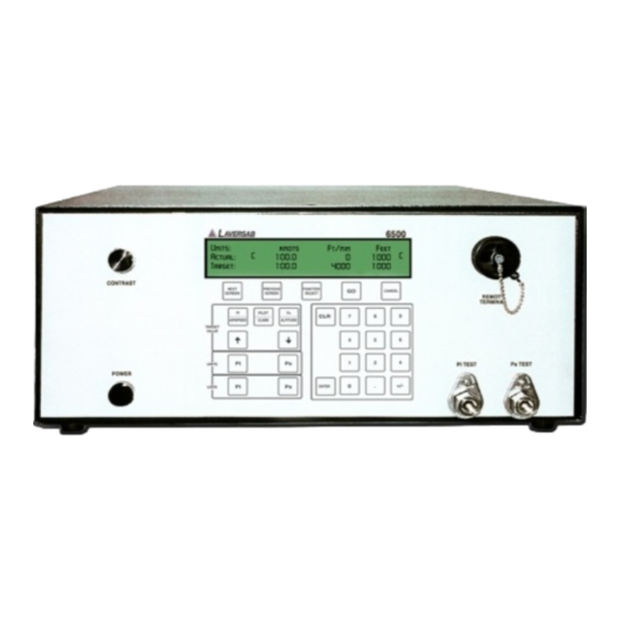
CONTROLS AND CONNECTIONS Note: Pt = Pitot and Ps = Static FRONT PANEL The front panel of the 6500 is shown in Figure 2.1 The various components of the front panel are described below. Power ON/OFF switch This is a Push On / Push Off switch. In the depressed position the switch in ON. This switch is used to connect AC power to the unit. - Page 12 There are five function keys just below the display. NEXT SCREEN and PREVIOUS SCREEN are used to move between the different operating screens of the 6500. At present there are only three upper level operating screens : Main, Calibrate and Self test.
- Page 13 The ENTER key is used to accept numeric entries and also select units and modes. TARGET VALUE KEYS : There are typically 3 parameters that the 6500 controls - Altitude, Climb and Airspeed. Each parameter has its own target value key. The Pt/AIRSPEED key is used to select Pt or Airspeed target value entry, the Ps RATE/CLIMB key is used to select Climb value entry, and the Ps/ALTITUDE key is used to select Ps or Altitude value entry.
-
Page 14: Rear Panel
For more information on Mode Selection please refer to Section 3.2.4. REAR PANEL The rear panel of the 6500 is shown in Figure 2.2 The various components of the front panel are described below. Vacuum Port (2 each) These ports are used for connecting a vacuum supply to the 6500. A vacuum supply of 0.3 inHg absolute or lower is ideal, and must be connected to both vacuum ports for proper operation. - Page 15 The 6500 will accept AC voltages between 90-260 VAC, 47-440 Hz. Typical power consumption is less than 80 VA. Caution: A power cord with a suitable Earth connection must be used to power the 6500 to prevent the possibility of a shock hazard.
- Page 16 6500 is operational. Caution: A Unit Under Test must not be connected to this port or disconnected from this port unless the 6500 is in Measure Mode. Caution: Do not connect the UUT to this port while performing the Self Test.
-
Page 17: Understanding The 6500
ON. DO NOT connect any UUT to the test ports. The 6500 will turn ON with two beeps. The display will briefly show the sign-on screen and then go into the Main screen. The Main screen should appear as follows:... - Page 18 Main Leak mode Leak Operating Screen Screen Function Select Function Select Screens (2) IEEE address View Limits Password Change Limits Change knots rate Execute profile (Return to Main) Setup Profile Height Correction Set Ground Go to Ground Encoder Next Screen Password Calibration Next...
-
Page 19: Main Operating Screen
6. MAIN OPERATING SCREEN Most of the operation of the 6500 is done in the Main Screen. All the pertinent parameters are displayed on this screen. The screen is also used to change Target values, Units, and Modes. - Page 20 The two values (1005 and 0) that appear below it are in these units. Units: knots Feet/min Feet Actual: 101.2 3500 1005 Target: 20.0 3000 Parameter 3. Climb Units: Unit of measurement for displaying the rate of change of the Static output, or Climb.
- Page 21 This is the value that you command the 6500 to achieve on the Pitot output (Pt test port). In the sample screen below, the 6500 has been commanded to achieve a pressure of 20.0 knots on the Pitot output. The Pitot “Target” value is meaningful only when the Pitot output is in the “Control”...
- Page 22 “Actual” value in the current Pitot units. The pressure is not being changed by the 6500. In this mode, the Pitot valve inside the 6500 that is used to change the pressure at the Pitot output is pneumatically isolated from the Pitot output. In the Measure mode, the Pitot “Target”...
- Page 23 “Actual” value in the current Static units. The pressure is not being changed by the 6500. In this mode, the Static valve inside the 6500 that is used to change the pressure at the Static output is pneumatically isolated from the Static output. In the Measure mode, the Static “Target”...
- Page 24 Static half Units: knots Feet/min Feet Actual: 101.2 3500 1005 Target: 20.0 3000 The Main operating screen will be used almost all the time during normal operation for commanding target values, viewing actual values, setting units and modes. Error Messages: The Main screen is also used to display error conditions as they occur.
-
Page 25: Target Value Entry
Pitot target value : A Pt or airspeed target value can be entered using the Pt/AIRSPEED key. On pressing this key the target value field for Pt gets put into reverse video. The 6500 is now awaiting numeric entry from the operator. While this new value is being entered, the old target value is still effective and does not in any way affect the Pitot output. - Page 26 Remote unit and the main unit. Please abort and contact the factory. If GO is pressed after ENTERing the value, the 6500 will try to achieve this new target value ONLY IF the Pitot output is in the CONTROL mode. Therefore, it is desired that both Pitot and Static values be entered so that both are blinking before the GO key is pressed.
-
Page 27: Units Selection
Target Value Jog Each of the three target values can be jogged up or down in small increments by using the arrow keys. This is done to help the operator achieve a perfect reading on the instrument in the aircraft, by bumping the set-point in small increments. To jog a value, select the value by pressing the appropriate target value key and then use the arrow keys. - Page 28 Target: 0.064 3000 The unit selection will not become effective until the GO key is pressed. The 6500 will return to the old units if the CANCEL key is pressed. . Static Units: There are four Ps units to choose from: Feet, Ps inHg (Psin), meters, and mbar (Psmb).
-
Page 29: Mode Selection
10.000 29.054 The unit selection will not become effective until the GO key is pressed. The 6500 will return to the old units if the CANCEL key is pressed. . It must be noted that the units change does not perform a conversion between the units of feet/minute or meters/minute to Ps inHg/min or Ps mbar/min. - Page 30 4 of the display, with the cursor under “MEAS”. Units: knots Feet/min Feet Actual: 101.2 3500 1005 Target: 20.0 3000 Pt mode : MEAS, LEAK, CTRL Move the cursor to the desired mode and then press ENTER. The selected mode is displayed on the screen and blinks until the GO key is pressed.
- Page 31 This process is termed as Equalization. While the 6500 is undergoing this process, the term 'EQZN' is displayed on the main screen in place of the “Actual” value. The whole process usually takes about 15 seconds or less to complete.
-
Page 32: Leak Screen
Following the Equalization process, only when the actual value on the Static output is less than 2000 feet from Ground and the Pitot output is less than 150 knots, the 6500 will automatically inject a small vacuum on the Static output and a small pressure on the Pitot output. - Page 33 Until the first minute has elapsed it shows “WAIT”. While in the Static Leak Screen, if the leak ever exceeds 2000 ft/min, the 6500 will automatically trip out of the Leak mode and revert back to Control mode. It will then display a message as follows: Static leak exceeds 2000 ft/min.
-
Page 34: Timed-Leak Screen
Pressing the CANCEL key allows you to exit from the Leak Screen, back to the Main Operating Screen. If the mode prior to entering the Leak mode was Control then the 6500 will revert back to Control mode on exiting the Leak Screen. - Page 35 100.0 knots 0 ft/min. 15000 feet 0:00 To accept the setting of the 1 leak-timer and move the arrow to the 2 leak-timer, press ENTER. The screen will appear as below. Change the 2 leak-timer value if desired, using the Arrow keys. The leak-timer value must be changed before the elapsed time reaches 58 seconds.
- Page 36 How the Timed-Leak screen is updated: The first line of the screen, which shows the current Actual values, is updated every 0.25 seconds. The elapsed time is updated every second. Assuming that the leak-timers are set to 1, 2 and 3 minutes, when the elapsed time reaches 1:02 (2 seconds after the elapsed time reaches the first leak-time) , the leak screen will be updated and appear as shown below.
-
Page 37: Self Test Screen
SELF TEST SCREEN As part of the start up procedure, it is recommended that a Self Test be performed on the 6500. Before performing the Self Test you must follow the start up procedure explained in section 3.1. The Main Operating Screen must be displayed on the Remote unit. There should be no errors displayed on line 4 of the display. -
Page 38: Function Select Screen
ROM OK RAM OK Ps measurement system OK Pt measurement system OK After the pump section test has passed successfully, the screen is cleared and the status of the remaining tests is displayed as shown below. Pump section OK Ps control system OK Pt control system OK. -
Page 39: Function 0: Ieee Address
3.5.0 FUNCTION 0 : IEEE ADDRESS This function allows the user to enter a valid IEEE-488 address for the 6500. This address is meaningful only if the “IEEE” option is provided on the 6500. A valid address between 1 and 30 may be entered on the screen shown below. -
Page 40: Function 2: Set Limits
If the target value exceeds any of the limits, an error is generated. The Actual values are also checked when the 6500 is in the “Control” mode. If any of these limits is exceeded by a pre-defined amount, an error will be generated and the 6500 will revert to “Measure” mode. - Page 41 2. Min. knots : This limits is usually negative and it defines the maximum “Negative Qc” that the airspeed instruments (UUT) can tolerate. In most cases it should be set to about “-200.0” since almost all airspeed indicators can tolerate at least that much negative Qc. Setting it any closer to “0.0”...
-
Page 42: Function 3: Set Knots Rate
This indicates that the current profile point is ready for execution and awaiting the “GO” key to be pressed. When the “GO” key is pressed, the 6500 will execute the profile point, i.e. it will change to Control mode and move towards the desired targets. -
Page 43: Function 5: Setup Profiles
3.5.5 FUNCTION 5: SETUP PROFILES This function is used to load profiles into the 6500 from a PC. A full explanation of how to load profiles into the 6500 is provided in Section 4.. The following screen will come up when Function 5 is selected. -
Page 44: Function 7: Set Ground
The “Set Ground” function is used to indicate to the 6500 the ambient “Ground” pressure. Before connecting the 6500 to the UUT, just after the Self Test has been performed, it is recommended that this function be invoked. The Pitot and Static ports must still be open to ambient when using this function. -
Page 45: Function 9: Encoder
If an altitude encoder is electrically connected to the Encoder interface connector on the rear panel of the 6500 (not shown in Fig. 2.2) and is pneumatically connected to the Ps output of the 6500, then the 10-bit code on line 2 and flight level on line 3 will correspond to the altimeter reading. -
Page 46: Profiles
4.1 WHAT IS A PROFILE. A profile is a set of up to 50 points that tell the 6500 what you would want it to do at each point. Each point consists of 7 parameters: 1) Pitot units, 2) Pitot mode, 3) Pitot target value, 4) Static units, 5) Static mode, 6) Static target value and 7) Static rate (Climb) target value. - Page 47 Rate target value In the sample profile, Row 3, which is the first point in the profile, tells the 6500 to go in Control mode to 100 knots on the Pitot side, and in Control mode to 0 feet at 6000 feet/min on the Static side.
-
Page 48: Creating A Profile
12 characters. On Row 2, middle cell, replace “11” with a profile number between 1 and 20 that you would like this profile to be saved as, in the 6500. Do not change row 2 right-most cell. In rows 3 through 50, change the cells as per the points you want to generate in your test. -
Page 49: Setting Up Hyperterminal
Your profile has been created. 4.3 SETTING UP HYPERTERMINAL You download a profile into the 6500 using the Hyperterminal program. At first you need to setup Hyperterminal. You only need to do this once. -
Page 50: Downloading A Profile
To verify that the 6500 file is setup in Hyperterminal, select “All Programs” from the desktop, select “Accessories”, select “Communications”, select “Hyperterminal”. The “6500” icon should appear. If it does not appear then you will need to repeat steps 1 and 2 above. -
Page 51: Executing A Profile
4.5 EXECUTING A PROFILE On the 6500, select Function 4: Execute profile. On line 4 on the Main screen, a profile number is required to identify the profile. This number is x.y where x is the profile number and y is the point number within that profile. - Page 52 When a profile goes into leak mode, the Leak Screen will be displayed. The profile will stay in this screen until the user enters CANCEL to exit the leak screen. The 6500 returns to the main screen where the user must press ENTER to invoke the next profile point.
-
Page 53: Typical Use
This section assumes that the user has read Section 3 and understood the functioning of the 6500. Please do not follow the sequence shown below without first reading Section 3. The following steps show a typical use of the 6500 for checking aircraft instruments. -
Page 54: Calibration
4.0 inHg abs. The 6500 has a drift of typically 0.005 %FS per year. Therefore it needs to be calibrated once a year to perform adequately as a calibration standard for air data equipment. -
Page 55: Ps Calibration
Step 2. Turn on the 6500 and allow it to warm up for about 30 minutes. Change the units to “PsinHg” on the Static side and “PtinHg” on the Pitot side. Refer to section 3.2.3 on how to change units. -
Page 56: Pt Calibration
Step 2. Turn on the 6500 and allow it to warm up for about 30 minutes. Change the units to “PsinHg” on the Static side and “PtinHg” on the Pitot side. Refer to section 3.2.3 on how to change units. - Page 57 Step 4. Generate a pressure of 100.000 inHg absolute, allow the pressure to stabilize for 2 minutes and take the reading on the Pt port (PtinHg) of the 6500. This is the second of your “Before” calibration adjustment reading. It will indicate the zero plus slope drift since the previous calibration.
- Page 58 Step 8. On the keypad of the remote unit, press “PREV SCREEN”. The display will return to the Main Screen. If you press “CANCEL” the calibration adjustment will become void. Step 9. Turn the 6500 OFF, wait 30 seconds and then turn it back ON. The calibration adjustment is now complete for the Pt port.
- Page 59 Model: 6500 Serial#: 74678 Full scale: Ps: 38 inHg Pt: 100 inHg Last Calibrated date: 10/10/01 _______________________________________________________________________ CALIBRATION RESULTS STATIC PRESSURE (Ps): TEST POINT AS FOUND AS LEFT DEVIATION inHg inHg inHg 1. Vacuum 1.001 1.000 0.001 2. Fullscale 38.002 38.000...
-
Page 60: Maintenance
SECTION 7 MAINTENANCE Scheduled maintenance of the 6500 includes calibration once a year. The calibration procedure is described in Section 6. In addition to calibration, there is only one other item that requires regular maintenance : replacing the fan intake filter as required. -
Page 61: Communication Interface
Connectors” cover on the top panel. This interface supports the following IEEE-488 functions. Source Handshake Acceptor Handshake Basic Talker Basic Listener Service Request Device Clear The IEEE-488 address of the 6500 can be changed using Function ‘0’ as described in Section 3.5.0. -
Page 62: Communication Syntax
Line Feed <LF>. To get data from the 6500 the unit must be addressed to Talk. Prior to asking the 6500 to Talk, the data to be sent by the 6500 must be specified through a command. For the 6500 to understand the command it must be in the Listen mode. - Page 63 Command Type Description PU=n Read/ Set Pt units as per following: units knots mach Pt inHg Qc inHg Pt mb Qc mb kmph SU=n Read/ set Ps units as follows: units Feet Ps inHg meters Ps mb PM=n Read/Set Pt mode to Measure (1), Leak (2), control (3) SM=n Read/set Ps mode to Measure (1), Leak (2), Control (3) Read current error ;...
- Page 64 Command Type Description Command to cancel current settings IE=n Read/set IEEE address C1=n Read/set Pt vacuum calibration point C2=n Read/set Pt fullscale calibration point C3=n Read/set Ps vacuum cal. point C4=n Read/set Ps fullscale calibration point Activate new calibration points after new values have been entered for either C1 and C2, or C3 and C4.
-
Page 65: Appendix A: Error Codes
APPENDIX A ERROR CODES All errors are displayed on line 4 of the display when the 6500 is in the Main screen. An error must be acknowledged before any other key entries are accepted. The error may be acknowledged either by pressing the CANCEL or the CLR key. -
Page 66: Appendix B: Specifications
APPENDIX B SPECIFICATIONS Static Output Pressure function range: 0.1 to 42 inHg resolution: 0.001 inHg accuracy: 0.002 inHg Altitude function range: -4000 ft. to 100,000 ft. resolution: 1 foot accuracy: 2 ft. @ 0 ft. 6 ft. @ 35,000 ft. 12 ft. -
Page 67: Appendix C: Repair And Return Policies
APPENDIX C REPAIR AND RETURN POLICIES If it is determined that the product is defective, please call Laversab customer service department: (281) 325-8300 or fax (281) 325-8399 or e-mail aservice@laversab.com for further assistance. Before shipping any equipment to Laversab for repair, please call the customer service department at (281) 325-8300 or fax (281) 325-8399 or e-mail to aservice@laversab.com.
Need help?
Do you have a question about the 6500 and is the answer not in the manual?
Questions and answers