
Related Manuals for Ameristar M4MHW15-A

Summary of Contents for Ameristar M4MHW15-A
- Page 1 INSTALLATION INSTRUCTIONS Single Zone Mini-Split Inverter System FEATURING R-410A 15 SERIES Single Split Indoor Unit Outdoor Unit Heat Pump M4MHW15-A M4THS15-A Cooling Only M4MCW15-A M4TCS15-A 88-M4MHW15-1A-EN...
- Page 2 Warnings and Cautions Warnings and Cautions. Warnings are provided to alert installing contractors to potential hazards that could result in severe personal injury or death, while cautions are designed to alert personnel to conditions that could result in minor or moderate injury. Your personal safety and the proper operation of this machine depend upon the strict observance of these precautions.
- Page 3 Warnings and Cautions WARNING R410-A Refrigerant under Higher Pressure than R-22! The units described in this manual uses R410-A refrigerant which operates at 50 to 70% higher pressures than R-22. Use only R-410A approved service equipment. Refrigerant cylinders are painted with "pink" color to indicate the type of refrigerant and may contain a "dip"...
-
Page 4: Table Of Contents
Contents Safety Precautions ........................5 Pre-Installation Checklist ......................6 Typical Installation Setup ......................7 Names and Functions of Each Part ................... 7 Clearance Requirements ......................8 Connection Pipe Requirements ....................9 Refrigerant Piping Precautions ....................10 Nitrogen Purging While Brazing ....................10 Installation Location ......................... -
Page 5: Safety Precautions
15 SEER Mini-Split Safety Precautions Warnings, Cautions and Notices: Warnings, cautions and notices appear at appropriate intervals throughout this manual. Warnings are provided to alert installing contractors to potential hazards that could result in serious injury or death. Cautions are designed to alert personnel to conditions that could result in minor to moderate injury. -
Page 6: Pre-Installation Checklist
15 SEER Mini-Split 12. During pump-down, stop the compressor before removing the refrigerant piping. If the compressor is still running and the stop valve is open during pump-down, air will be sucked in when the refrigerant piping is removed, causing abnormal pressure in the refrigerant cycle which could lead to breakage and injury. -
Page 7: Typical Installation Setup
15 SEER Mini-Split Typical Installation Setup (10) (Sold Separately) (10)Wired controller * Field provided... -
Page 8: Clearance Requirements
15 SEER Mini-Split Clearance Requirements Space to the ceiling 6 in. or more Space to the wall 6 in. or more 6 in. or more Space to the wall 118 in. or more or more Air outlet side Space to the floor The dimensions of the space necessary for correct installation of the appliance including the minimum permissible distances to adjacent structures... -
Page 9: Connection Pipe Requirements
15 SEER Mini-Split Connection Pipe Requirements NOTICE The maximum length of the connection pipe is listed in the table below. Do not place the units such that the distance between them exceeds the maximum length of the connection pipe. M4THS1509A M4THS1512A M4THS1518A M4THS1524A... -
Page 10: Refrigerant Piping Precautions
15 SEER Mini-Split Refrigerant Piping Precautions WARNING Hazard of Explosion and Deadly Gases! Failure to follow all proper safe refrigerant handling practices could result in death or serious injury. Never solder, braze or weld on refrigerant lines or any unit components that are above atmospheric pressure or where refrigerant may be present. -
Page 11: Installation Location
15 SEER Mini-Split Installation Location Indoor Unit WARNING Adequate Support Required! The wall structure must be adequate to support the weight of the unit. Failure to ensure adequate structural support could result in the unit falling from its location which could result in death, serious injury, or equipment or property damage. -
Page 12: Installing The Indoor Unit
15 SEER Mini-Split Installing the Indoor Unit WARNING Hazardous Service Procedures! The maintenance and troubleshooting procedures recommended in this section of the manual could result in exposure to electrical, mechanical or other potential safety hazards. Always refer to the safety warnings provided throughout this manual concerning these procedures. -
Page 13: Drilling The Piping Hole
15 SEER Mini-Split Drilling the Piping Hole The piping can be connected in the direction of right, rear right, left or rear left. Left Right Cut off Rear left the hole Right 1. When the position of the drain piping has been selected, cut out the corresponding knock-out from the unit housing. - Page 14 15 SEER Mini-Split 1. When connecting refrigerant pipe to the unit or removing it from the unit, please use both a back-up wrench and the torque wrench. See illustration below. 2. When connecting, place oil on the backside of the copper tube flare prior to tightening. Do not place oil on the flare face, as this will promote system contamination, tighten it by hand and then tighten it with the spanner.
-
Page 15: Installing The Condensate Pipe
15 SEER Mini-Split Installing the Condensate Pipe NOTICE Do not wrench or bend the drain hose and make sure the ends of the condensate pipe are not under water. Failure to do so could result in leakage. 1. Connect the drain hose to the outlet pipe of the indoor unit (as shown in Fig. A below). 2. - Page 16 15 SEER Mini-Split 3. Remove the wire clip and connect the power connection wire to the wiring terminal according to the correct color coding. Using 4 wire colors (for example: Black, Blue, Red, Green) Connect Black to 1, Blue to 2, Red to 3 and Green to Ground. All wiring shall use ring or spade type crimped or soldered connectors to assure communication is not interrupted.
-
Page 17: Binding The Pipes And Cables
15 SEER Mini-Split Binding the Pipes and Cables Note: The refrigeration lines shall be insulated separately to prevent heat transfer between the two lines. Both lines shall be insulated. 1. Bind the insulated refrigerant pipes, power cord and drain hose with a band. 2. -
Page 18: Installing The Outdoor Unit
15 SEER Mini-Split Installing the Outdoor Unit WARNING 1. Install the unit where it will not be tilted by more than 5° 2. If the location is subject to strong winds, the additional force must be accounted for and the unit must be fixed securely to the base. When the outdoor unit is surrounded by walls or other obstructions, the installation space of the unit should be no less than the clearances indicated below. -
Page 19: Installing The Refrigerant Piping
15 SEER Mini-Split 1. Place the outdoor unit on the support base. 2. Secure the foot holes of the outdoor unit with bolts (as shown below). Foot holes Foot holes Installing the Refrigerant Piping Flaring Process 1. Hold the pipe downward to prevent cuttings from entering the pipe. 2. -
Page 20: Refrigerant Piping At The Outdoor Unit
15 SEER Mini-Split 4. Do not bend the pipe while it is encased in the insulation. In this case, cut the insulation with a sharp cutting tool as shown below, and bend it after exposing the pipe. After bending is complete, assure the insulation wrapping is sealed. -
Page 21: Piping Requirements
15 SEER Mini-Split Piping Requirements If the outdoor unit is installed lower than the indoor unit: 1. A drain pipe should be above ground and the end of the pipe should not dip into water. 2. Taping pipes must be done from bottom to top. Do not wrap too tightly to avoid compression of the insulation, which would reduce the effectiveness. -
Page 22: Vacuum And Refrigerant Leakage Detection
15 SEER Mini-Split Vacuum and Refrigerant Leakage Detection NOTICE Do not purge the air with refrigerant. Use a vacuum pump to vacuum the installation! There is no extra refrigerant in the outdoor unit for air purging! Vacuum 1. Remove the caps of the liquid valve, gas valve and service port. 2. -
Page 23: Wiring Precautions
15 SEER Mini-Split Wiring Precautions WARNING 1. Before obtaining access to terminals, all supply circuits must be disconnected. 2. Improperly installed and grounded field wiring poses fire and electrocution hazards. For high voltage connections, flexible electrical conduit is recommended whenever vibration transmission may create a noise problem within the structure. -
Page 24: Stranded Wiring Connections
15 SEER Mini-Split Stranded Wiring Connections 1. Cut the wire end with a wire cutter or wire cutting pliers, then strip the insulation about 3/8" (10mm). 2. Using a screwdriver, remove the terminal screw(s) on the terminal board. 3. Using crimp or solder connections, securely attach a round terminal to each stripped wire end. 4. -
Page 25: Electrical Connections
15 SEER Mini-Split Electrical Connections CAUTION Improper operation may lead to personal injury or property damage. Be sure to size the power supply wiring according to the NEC, local code and the MCA indicated on the unit nameplate. Electrical Requirements Heat Pump Models M4THS1509 M4THS1518... -
Page 26: Cable Specifications
15 SEER Mini-Split Cable Specifications Wiring between the indoor and outdoor unit should be at least 14 AWG / 600 volt rated / stranded wire; 4 conductors are required. Be sure to consult local and regional codes, as well as the NEC, for installation requirements that are applicable to the selected type of cable including watertight conduit and raceway requirements. -
Page 27: Post Installation Checklist
15 SEER Mini-Split Post Installation Checklist Check the following points before testing the unit: Item to be checked Possible problem Have the indoor and outdoor units been The units may fall, vibrate or make noise. securely installed? Has the refrigerant leak test been Unresolved leaks may cause insufficient completed? cooling or heating and low pressure errors. -
Page 28: Refrigerant System Diagrams
15 SEER Mini-Split Refrigerant System Diagram Cooling Only Models Outdoor unit Indoor unit Gas pipe side Valve Di s charge Heat exchanger (evaporator) Suction Accumlator Compressor Heat exchanger Liquid pipe (condenser) side Valve Capillary Strainer Heat Pump Models Indoor unit Outdoor unit Gas pipe side... -
Page 29: Wiring Diagrams
15 SEER Mini-Split Wiring Diagrams Color Key Symbol Symbol Color Symbol Symbol Color Symbol Name White Green Jumper cap Yellow Brown COMP Compressor Blue Grounding wire YE/GN Yellow/Green Black Violet Orange Note: Jumper cap is used to determine fan speed and the swing angle of horizontal louver for this model. - Page 30 15 SEER Mini-Split Outdoor Cooling Only Unit 9K-12K N(1) NOTE: Motor ground only applies to metal clad motors. Outdoor Heat Pump Only Unit 9K-12K N(1) NOTE: Motor ground only applies to metal clad motors. These diagrams are subject to change without notice, please refer to the diagram supplied with the unit. NOTE: The wiring diagrams in this guide are included as a reference.
- Page 31 15 SEER Mini-Split Outdoor Cooling Only Unit 18K-24K N(1) Outdoor Heat Pump Only Unit 18K-24K N(1) These diagrams are subject to change without notice, please refer to the diagram supplied with the unit. NOTE: The wiring diagrams in this guide are included as a reference. The manufacturer has a policy of continuous product and product data improvement and reserves the right to change design and specifications without notice.
-
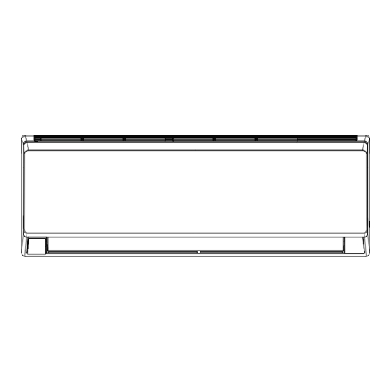
Page 32: Unit Dimensions
15 SEER Mini-Split Indoor Unit Dimensions 9K-12K Indoor Units 6 5/8 18 3/16 6 5/16 Φ2 3/16 Φ2 3/16 2 1/8 2 1/8 3 1/2 4 11/16 21 5/16 7 1/4 Φ2 3/16 Φ2 3/16 1 3/8 1 3/8 3 5/16 Unit:inch MODEL 31 1/9... - Page 33 15 SEER Mini-Split Indoor Unit Dimensions, continued 18K-24K Indoor Units 3/16 Φ2 3/16 Φ2 3/16 1 1/2 7 1/2 5 1/2 8 1/8 7 5/16 Φ2 3/4 Φ2 3/4 1 11/16 3 1/8 Unit:inch Models 38 1/5 11 4/5 8 5/6 42 4/9 12 4/5 9 2/3...
- Page 34 15 SEER Mini-Split Outdoor Unit Dimensions 9K-12K Outdoor Units 10 1/8 12 3/5 30 5/9 18K-24K Outdoor Units 13 3/8 15 5/8 Unit: inch...
-
Page 35: Common Error Codes
15 SEER Mini-Split Common Error Codes Error Code Malfunction Type Recommendation AC over current protection Restart the unit. If the error does High temperature protection E8 / H4 not clear, contact your dealer. Indoor fan motor error Jumper cap malfunction protection Indoor ambient sensor open or short circuit Contact your dealer Indoor tube sensor open or short circuit... -
Page 36: Troubleshooting
15 SEER Mini-Split Troubleshooting CAUTION Improper operation may lead to personal injury or casualty. • Turn off the main power switch immediately if a malfunction is detected. Contact your servicing or installing dealer. If the unit continues to run during a malfunction, the unit may be damaged or electric shock or fire may occur. -
Page 37: Maintenance Of The Indoor Unit
15 SEER Mini-Split Maintenance of the Indoor Unit 1. Clean the outer surface of the unit with a dry or damp cloth. 2. If there is residue, the unit may be cleaned with a mild detergent solution. Do not use chemical solvents or flammable liquids to clean the surface of the unit. -
Page 38: General Maintenance
15 SEER Mini-Split General Maintenance Regular checks, maintenance and care should be performed by professional personnel, which will prolong the unit life span. Outdoor Heat Exchanger The outdoor heat exchanger should be checked and cleaned once every two months. Use a vacuum cleaner with a nylon brush to clean up dust and debris on the surface of the heat exchanger. - Page 40 CONFORMSTO ULSTD.1995 CERTIFIEDTO CSASTD.C22.2 Literature Order Number 88-M4MHW15-1A-EN Intertek N0.236 Date December 2016 3097844 Supersedes The manufacturer has a policy of continuous product and product data improvement and reserves the right to change design and specifications without notice. Only qualified technicians should perform the installation and ©...
Need help?
Do you have a question about the M4MHW15-A and is the answer not in the manual?
Questions and answers
looking for a replacement filter for a M4MHW15-A
If the filter for the Ameristar M4MHW15-A cannot be adequately cleaned, you should contact your dealer for a replacement filter. Specific replacement filter options are not listed in the provided information.
This answer is automatically generated