Table of Contents
Advertisement
Advertisement
Table of Contents

Related Manuals for Powersmart DB7651-24


Summary of Contents for Powersmart DB7651-24
- Page 1 INSTRUCTION MANUAL 24 inch Two Stage Gas Snow Thrower Model # DB7651-24 Have product questions or need technical support? Please feel free to contact us! Website: www.Amerisuninc.com Toll free: 1-800-791-9458 Mon-Fri 9-5 EST Email: support@amerisuninc.com...
-
Page 3: Table Of Contents
Troubleshooting…………………………………………………………. Exploded view and parts list……………………………………………... 27 Two (2) years limited warranty……………………...…………………… 33 TECHNICAL DATA 24 inch Two Stage Electric Start Snow Thrower Model #: DB7651-24 Engine: 212cc Snow Engine Engine oil Capacity: 16 fl.oz Fuel Tank Capacity: 0.66 Gallon... -
Page 4: Introduction
INTRODUCTION ® Thank You for Purchasing a PowerSmart Product. This manual provides information regarding the safe operation and maintenance of this product. Every effort has been made to ensure the accuracy of the ® information in this manual. PowerSmart reserves the right to change this product and specifications at any time without prior notice. - Page 5 TRAINING Read, understand, and follow all instructions on the machine and in the manual(s) before attempting to assemble and operate. Keep this manual in a safe place for future and regular reference. • Be familiar with all controls and their proper operation. Know how to stop the machine and disengage them quickly.
- Page 6 • Read, understand and follow all instructions on your Snow Thrower and in this Operator's Manual before attempting to assemble and operate your machine. • Keep this manual in a safe place for future and regular reference. If replacement parts are needed, refer to the manual.
- Page 7 • Never store the machine or fuel container inside where there is an open flame, spark or pilot light (e.g. furnace, water heats, space heater, clothes dryer etc.). • Allow machine to cool at least 5 minutes before storing. • Never fill containers inside a vehicle or on a truck or trailer bed with a plastic liner.
- Page 8 • Disengage power to the auger impeller when transporting or not in use. • Never operate machine at high transport speeds on slippery surfaces. Look down and behind and use care when backing up. • If the machine should start to vibrate abnormally, stop the engine, disconnect the spark plug wire and ground it against the engine.
- Page 9 • Check control levels periodically to verify they engage and disengage properly and adjust, if necessary. Refer to the adjustment section in this operator's manual for instructions. • Maintain or replace safety and instruction labels, as necessary. • Observe proper disposal laws and regulations for gas, oil, etc. to protect the environment. •...
-
Page 10: Knowing Your Snow Thrower
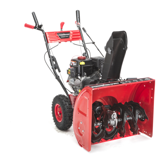
KNOWING YOUR SNOW THROWER Use the illustrations below to become familiar with the locations and functions of the various components and controls of this snow thrower. Drive Control Handle Skid Shoe Speed Control Lever Tire Auger Control Handle Oil Drain Bolt Chute Rotation Handle Belt Cover Fuel Tank Cap... - Page 11 21 22 Auger Housing Switch Key Clean-out Tool Handle Knob Discharge Chute Deflector Choke Lever Discharge Chute Recoil Starter Handle Chute Base Primer Bulb Drive Control Handle Located on the right side of the upper handle, the Drive Control Handle is used to engage and disengage the drive wheels.
- Page 12 Skid Shoe Position the shoes based on the surface conditions. Adjust upward for hard-packed snow. Adjust downward when operating on gravel or crushed rock surfaces. Augers and Impeller When engaged, the augers rotate to cut snow and direct it into the impeller housing to be discharged out the chute.
-
Page 13: Assembly And Adjustments
ASSEMBLY AND ADJUSTMENTS The following section describes steps necessary to prepare the snow thrower for use. If after reading this section, you are unsure about how to perform any of the steps please call (800) 791-9458 Mon-Fri 9-5 EST for customer service. Failure to perform these steps properly can damage the snow thrower or shorten its life. - Page 14 Step 2 – Chute assembly 1. Remove the bolt and nut from the chute base. 2. Slide the chute into the chute base. Note: The chute slides into the base, if the chute fits tightly use a light lubricant to assist installation. In some cases, the chute lip may have excess material from manufacturing, it is acceptable to carefully remove some material from the chute lip in order to allow the chute to slide into the chute base.
-
Page 15: Snow Thrower Preparation
Step 4 – Skid shoes installation and adjustments 1. Locate the pair of skid shoes from parts bag and remove the bolts. 2. Loosely install the skid shoes using the bolts and hex nuts as shown on each side of the auger housing. Make sure the skid shoe tip faces out. - Page 16 WARNING! DO NOT USE YOUR HANDS TO UNCLOG CHUTE. Stop the motor before removing debris. Use the supplied clean out tool to unclog the chute. Do not walk in front of your running Snow Thrower. Do not direct discharged snow towards bystanders. •...
- Page 17 DRIVE SPEED CONTROL LEVER Move the drive speed control lever to the desired speed. There are six (6) settings: four (4) forward speeds and two (2) reverse speeds. 1 is the slowest forward speed and 4 is the fastest forward speed. R1 is the slowest reverse speed and R2 is the fastest reverse speed.
-
Page 18: Operating Your Snow Thrower
OPERATING YOUR SNOW THROWER STARTING Please refer to ENGINE manual (separate document) for engine operation instructions. CLEARING SNOW Start the engine (see ENGINE manual) once your Snow Thrower has been running outside for several minutes, it is now ready for use. Make sure the path in front of your Snow Thrower is free from people, animals, objects, and all other obstructions except for snow. -
Page 19: Maintenance
MAINTENANCE WARNING! Never perform maintenance while your Snow Thrower is running. Turn OFF the engine before performing any maintenance tasks on your Snow Thrower. Proper maintenance of your Snow Thrower will help prolong its life. Please perform the following maintenance procedures as required. Please read the ENGINE manual for engine maintenance procedures. - Page 20 4. Wait until the auger and impeller have come to a full stop. 5. Clear any visible jams using the clean out tool attached to your machine. WARNING! DO NOT try to clear jams with your hands or feet. AUGER SHEAR PINS REPLACEMENT Shear pins are used to attach the auger shaft to the auger blades.
- Page 21 2. Loosen the jam nuts on each cable (only one or two threads) and move each cable up and down as required until a positive direction change is achieved when the lever is shifted between F1 and R1. This may take multiple attempts to find the exact setting. 3.
- Page 22 2. Push the auger tension pulley arm to move the auger brake to allow access for installation of the belt into the auger pulley. 3. Route the belt to the inside of the tension pulley, auger brake and install the auger belt onto the drive pulley while pulling the auger housing into position with the main frame.
-
Page 23: Storage & Cleaning
• Does the tension arm move freely both engaged and disengaged directions without binding? • Misaligned tension pulley, the pulley should move parallel to the belt centered to the belt • Check return spring operation and tension Inspect the auger engagement handle and cable: •... -
Page 24: Troubleshooting
TROUBLESHOOTING Problem Causes Remedy WARNING - Before attempting to make any inspections, repairs or adjustments, stop the engine, wait for all moving parts to stop moving and carefully disconnect the engine spark plug wire. If tipping or turning the snow blower is required for any inspection or repair, first wait until the engine is cool to the touch and then drain the engine of all fuel and oil into suitable containers and store or dispose of in a proper manner. - Page 25 Problem Causes Remedy Drive system Check drive belt tension pulley for damage or incorrect tension, repair as necessary. Replace No forward or Drive belt loose or damaged drive belt. reverse drive movement when Friction drive wheel is worn or damaged Replace friction drive wheel drive handle Allow snow blower to dry and or warm up or...
- Page 26 Problem Causes Remedy Auger System Auger tension pulley arm return spring broken or missing Replace tension arm return spring Auger tension pulley arm stuck or binding Repair or replace tension arm as necessary Auger tension pulley arm or pulley Repair, replace or align tension arm and or misaligned or damaged pulley as necessary Auger belt broken,...
-
Page 27: Exploded View And Parts List
EXPLODED VIEW AND PARTS LIST Panel Assembly (All Parts Number Begin with P) Item Stock # Description Item Stock # Description 303020106 Flange Screw M8×20 303070272A Drive Control 303080442 Lower Handle 303020297 Screw M6×40 303200092 Auger Lower Cable 303030025 Nut M6 303200093 Drive Lower Cable 303030077... - Page 28 Chute Assembly (All Parts Numbers Begin with C) Item Stock # Description Item Stock # Description 303043010 Saddle Washer 8 303121011 Cotter Pin 303050029 Closing Ring M10 203010147 Discharge Chute Seat Chute Direction Control 203020371 203050049 Middle Discharge Chute Knob 303042039 Flat Washer M10×20×2 203050058...
- Page 29 Frame Assembly (All Parts Number Begin with F)
- Page 30 Item Stock # Description Item Stock # Description 303020492 Flange Screw M6×10 303122002 Dowel Pin 303042001 Flat Washer 6×16×1.5 302090139 Wheel Elastic Cylindrical Pin 303160308 Spacer 303123008 5x30 303042039 Flat Washer 10×20×2 303110022 Woodruff Key 303041015 Spring Washer 10 303070134A Guide Roller Bracket 303030068 Nut M10x1...
- Page 31 Auger Housing Assembly (All Parts Number Begin with H)
- Page 32 Item Stock # Description Item Stock # Description 303180424 Single Auger Blade R 303020166 Square Neck Bolt M8×18 202450076 Gear Housing Assembly 303020332 Square Neck Bolt M8×16 H02-1 303090031 Gear Housing R 303030077 Locknut M8 H02-2 303020142 Plug Screw M8x10 303070936 Shave Plate H02-3...
-
Page 33: Two (2) Years Limited Warranty
Limited Warranty, you must return the entire power tool product; transportation prepaid, to PowerSmart Include a legible copy of the original receipt, which lists the date of purchase (month and year) and the name of the company purchased from.
Need help?
Do you have a question about the DB7651-24 and is the answer not in the manual?
Questions and answers
what is the spark plug gap for a 12 year old 212cc snowblower
The spark plug gap for a PowerSmart DB7651-24 212cc snowblower is not specified in the provided context.
This answer is automatically generated
What type of oil is best for this model
The use of automotive synthetic oil is acceptable for the Powersmart DB7651-24.
This answer is automatically generated