Advertisement
Questions, problems, missing parts?
Amerisun customer service department at 1-800-791-9458 or visit Amerisuninc.com and e-mail
support@amerisuninc.com. For engine related problems, questions and warranty service call the engine
manufacturer 1-877-274-2214.
WARNING! Read and follow all safety rules and instructions in this manual before attempting to operate this
machine. Failure to comply with these instructions may result in personal injury. Save these instructions. This
unit is equipped with an internal combustion engine and may spark resulting in fire or explosion if used near
combustible material or fluid. Only use when the engine's exhaust system is equipped with a spark arrester
meeting applicable local or state laws (if any). The spark arrester shall be maintained in effective working
order by operator.
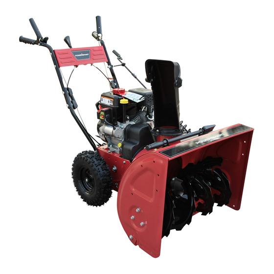
TWO STAGE GAS SNOW THROWER
If you have questions or need technical support, call the
MODEL DB7651-24, 26 and 28
Advertisement
Table of Contents

Related Manuals for Powersmart DB7651-24


Summary of Contents for Powersmart DB7651-24
- Page 1 TWO STAGE GAS SNOW THROWER MODEL DB7651-24, 26 and 28 Questions, problems, missing parts? If you have questions or need technical support, call the Amerisun customer service department at 1-800-791-9458 or visit Amerisuninc.com and e-mail support@amerisuninc.com. For engine related problems, questions and warranty service call the engine manufacturer 1-877-274-2214.
-
Page 2: Table Of Contents
TABLE OF CONTENTS Safety............................... 2 Feature Identification ..........................6 Box Contents ............................7 Assembly ..............................7 Operation ..............................10 Operating Your Snow Thrower ....................... 12 Maintenance ............................13 Accessories ............................22 Troubleshooting ............................23 Warranty ..............................25 DISCLAIMER The information contained within this manual is the latest information as of the publication date. All content and images are subject to change without notice. -
Page 3: Safety
SAFETY Preparation Thoroughly inspect the area where the This symbol points out important safety equipment is to be used. Remove all doormats, instructions which, if not followed, could newspapers, sleds, boards, wires and other endanger the personal safety and or foreign object, which could be tripped over or property of yourself and others. - Page 4 • Exercise caution to avoid slipping or falling, • Never fill containers inside a vehicle or on a truck or especially when operating in reverse. trailer bed with a plastic liner. Always place • Stay alert, watch what you are doing and use containers on the ground away from your vehicle common sense when operating your Snow Thrower.
- Page 5 • If the machine should start to vibrate abnormally, • Maintain or replace safety and instruction labels, as stop the engine, disconnect the spark plug wire and necessary. ground it against the engine.Inspect thoroughly for • Observe proper disposal laws and regulations for damage.
- Page 6 Safety Symbols This page depicts and describes safety symbols that may appear on this product. Read, understand and follow all instructions on the machine before attempting to assemble and operate.
-
Page 7: Feature Identification
FEATURE IDENTIFICATION TECHNICAL SPECIFICATIONS Clearing Width: DB7651 24, 26 and 28 inches Clearing Height: 21 inches 4 Forward and 2 Reverse Speeds Engine Displacement: 208 cc, 4 stroke A - Drive Control Handle E - Engine I - Snow/Ice Clean Out Tool B - Speed Control Lever F - Skid Shoe J - Chute Assembly... -
Page 8: Box Contents
A. Drive Control Handle Shave Plate (not shown) Located on the right side of the upper handle, the The Shave Plate maintains contact with Drive Control is used to engage and disengage pavement as the snow thrower is propelled, the drive wheels. Squeeze the Drive Control allowing snow close to pavement's surface to be handle against the upper handle to engage the discharged. - Page 9 2. Securely install the supplied screw, washer and hex nut. NOTICE: Do not bend or kink the control cables. The cables should be routed under the handle assembly and not wrapped around the handle or knobs. The cables must move freely and not bind. 3.
- Page 10 Chute Rotation Handle Assembly and Installation 1. Connect the chute rotation handles (upper and lower) using screws provided. 2. Install the stepped washer into the hole on the Skid Shoe Installation and bracket. Install the lower rod end of the chute Adjustment rotation handle through the hole and stepped 1.
-
Page 11: Operation
• Determine the direction of the wind. If possible, move in the same direction as the wind so that the snow is not thrown against the wind, back into your face and on the just cleared path. WARNING! DO NOT USE YOUR HANDS TO UNCLOG CHUTE. - Page 12 Auger and Drive Controls Drive Speed Control Lever 1. To engage the auger, press down on the Move the drive speed control lever to the desired auger control handle (left side handle). speed. There are six (6) settings: four (4) forward speeds and two (2) reverse speeds.
-
Page 13: Operating Your Snow Thrower
OPERATING YOUR SNOW THROWER Starting Please refer to ENGINE manual (separate document) for engine operation instructions. Clearing Snow Start the engine (see ENGINE manual) once your Snow Thrower has been running outside for Chute Discharge Angle Adjustment several minutes, it is now ready for use. Make sure the path in front of your Snow Thrower is WARNING! Always disengage the drive and free from people, animals, objects, and all other... -
Page 14: Maintenance
move or throw. Wet snow will tend to clog and Check the bolts at frequent intervals for proper stick more to the augers and chute. Keep the tightness to ensure that the equipment is in safe auger engaged as much as possible when working condition. - Page 15 Auger Shear Pin Replacement Shear pins are used to attach the auger shaft to the auger blades. A clog or jam in the augers may cause one or multiple shear pins to break. The shear pins are a safety mechanism and designed to break under high load or impact to protect the auger drive system from damage.
- Page 16 Drive Control Cable Tension Adjustment WARNING! Entanglement Hazard - Before performing any adjustment procedures, make sure the engine is off and remove the spark plug wire from the spark plug to ensure the engine cannot accidently start. Never adjust cable tension with the engine running. The drive control cable is located on the right side (when standing behind the snow blower) and is made up of an upper and lower cable...
- Page 17 6. Start the engine and engage the drive control handle to test the operation of the drive engagement. Note: With the drive control handle at the full released position, the cable should be barely tight. Some slack in the cable may be required to ensure the drive control is not engaging the drive friction wheel.
- Page 18 Auger Belt Tension Adjustment The auger cable is located on the left side (when standing behind the snow blower) and is made WARNING! Entanglement Hazard - Before up of an upper and lower cable connected by an performing any adjustment procedures, make adjustment plate.
- Page 19 4. Adjustment is made by changing the position of the lower cable in the adjustment plate holes (1 to 9). Only move the lower cable diagonally 2. Remove 2 hex head screws and remove belt one hole at a time from its original position. cover.
- Page 20 6. Remove the belt from the drive pulley while pulling the right side of the auger housing away from the main frame just enough to access the belt and auger pulley. 4. Left Side - Loosen the hex nuts attaching the auger housing to the main frame.
- Page 21 1. Inspect the new belt to ensure it is the correct size and type. • Original - Gates Truflex G 4LXP885 • Alternate - MTD 954-0101A 2. Push the auger tension pulley arm to move the auger brake to allow access for installation of the belt into the auger pulley.
- Page 22 Auger Belt and Related Component • Free movement (from engage to disengaged positions) Inspection • Binding or improperly routed cable When replacing your snow blower auger belt it is • Cable pulley(s) damage, misalignment and binding important to determine the cause of the failure (if •...
-
Page 23: Accessories
ACCESSORIES Drift Cutters Drift cutters are optional accessories and may be included with some models with pre-drilled holes in the sides of the auger housing. Installation is optional. Drift cutters are used to help cut through snow drifts that are higher than the auger housing and allow the cut snow to fall into the auger housing. -
Page 24: Troubleshooting
TROUBLESHOOTING Problem Possible Causes Remedy WARNING - Before attempting to make any inspections, repairs or adjustments, stop the engine, wait for all moving parts to stop moving and carefully disconnect the engine spark plug wire. If tipping or turning the snow blower is required for any inspection or repair, first wait until the engine is cool to the touch and then drain the engine of all fuel and oil into suitable containers and store or dispose of in a proper manner. - Page 25 Drive System 1 Drive control cable loose, broken or binding 1 Repair or adjust drive control cable and adjust tension, see Auger and Drive Cable Adjustment 2 Drive belt loose or damaged 2 Check drive belt tension pulley for damage or incorrect tension, repair as necessary. Replace drive belt. No forward or reverse 3 Friction drive wheel is worn or damaged 3 Replace friction drive wheel...
-
Page 26: Warranty
WARRANTY TWO YEAR WARRANTY ENGINE WARRANTY See the ENGINE manual included with this snow thrower for engine warranty information. For all engine related warranty issues contact LCT engine corporation - phone 1-877-274-2214. WARRANTY For two years from date of retail purchase within U.S.A., the manufacturer will, at its option, repair or replace, for the original purchaser, free of charge, any part or parts found to be defective in material or workmanship.
Need help?
Do you have a question about the DB7651-24 and is the answer not in the manual?
Questions and answers