Table of Contents
Advertisement
Advertisement
Table of Contents

Subscribe to Our Youtube Channel
Related Manuals for Hantek DSO5000 Series

Summary of Contents for Hantek DSO5000 Series
- Page 1 DSO5000 Series Digital Storage Oscilloscope User Manual...
-
Page 2: Table Of Contents
TTENUATION ETTING .......................8 ALIBRATION CHAPTER 4..................MAIN FEATURE DESCRIPTION 9 ......................9 SCILLOSCOPE ETUP ..........................9 RIGGER ......................11 CQUISITION ................11 AVEFORM CALING AND OSITIONING ....................12 AVEFORM EASUREMENT CHAPTER 5......................BASIC OPERATION 14 ........................15 ISPLAY 5.1.1 XY Format........................16 DSO5000 Series Digital Storage Oscilloscope User Manual... - Page 3 EASURE ULSE IGNAL 6.10 10: U ........58 XAMPLE SING UNCTIONS TO NALYZE AVEFORMS 6.11 11: M ............59 XAMPLE EASURING ROPAGATION ELAY CHAPTER 7....................TROUBLESHOOTING 61 ......................61 ROBLEM ETTLEMENT CHAPTER 8......................SPECIFICATIONS 62 ....................62 ECHNICAL PECIFICATIONS DSO5000 Series Digital Storage Oscilloscope User Manual...
- Page 4 Contents ........................67 CCESSORIES CHAPTER 9..................SERVICES AND SUPPORT 69 CHAPTER 10................GENERAL CARE AND CLEANING 70 10.1 .........................70 ENERAL 10.2 ..........................70 LEANING APPENDIX A HARMFUL AND POISONOUS SUBSTANCES OR ELEMENTS......71 Appendix B Index...........................72 DSO5000 Series Digital Storage Oscilloscope User Manual...
-
Page 5: Copyright Declaration
Hantek reserves all rights to modify this document without prior notice. Please contact Hantek for the latest version of this document before placing an order. Hantek has made every effort to ensure the accuracy of this document but does not guarantee the absence of errors. Moreover, Hantek assumes no responsibility in obtaining permission and authorization of any third party patent, copyright or product involved in relation to the use of this document. -
Page 6: Chapter 1
Do not operate with suspected failures. If you suspect there is damage to this product, have it inspected by qualified service personnel. Assure good ventilation. Do not operate in wet/damp environments. Do not operate in an explosive atmosphere. Keep product surfaces clean and dry. DSO5000 Series Digital Storage Oscilloscope User Manual... -
Page 7: Safety Terms And Symbols
Terminal Mains Mains High Voltage Disconnected Connected OFF (Power) ON (Power) 1.5 Product Scrapping Device Recycling We need extract and utilize natural resources to produce this device. If you do not reclaim the DSO5000 Series Digital Storage Oscilloscope User Manual... - Page 8 To avoid them being released outside and to minimize the waste of natural resources, we suggest you reasonably call back this device to ensure proper recovery and recycling of most materials within it. DSO5000 Series Digital Storage Oscilloscope User Manual...
-
Page 9: Chapter 2
7 inch color Table 2-1 Model List of DSO5000 Series DSO5000 Series oscilloscopes cover the bandwidths from 60MHz to 200MHz, and provide the real-time and equivalent sample rates respectively up to 1GSa/s and 25GSa/s. In addition, they have maximum 1M memory depth for better observation of the waveform details, and 7 inch color TFT LCD as well as WINDOWS-style interfaces and menus for easy operation. - Page 10 Turn the HELP SCROLL knob to highlight a help topic. Press the Show Topic option button to display the topic. NOTE: Press the Exit option button or any menu button to remove the Help text from the screen and return to displaying waveforms. DSO5000 Series Digital Storage Oscilloscope User Manual...
-
Page 11: Chapter 3
Follow the steps below to perform a quick functional check to your oscilloscope. 3.2.1Power on the oscilloscope Plug in the oscilloscope and press the ON/OFF button. Then push the DEFAULT SETUP button. The default Probe option attenuation setting is 10X. The Default Setup button DSO5000 Series Digital Storage Oscilloscope User Manual... -
Page 12: Connect The Oscilloscope
Press the AUTOSET button and you should see within a few seconds a square wave of about 5V peak-to-peak at 1kHz in the display. Press the CH1 MENU button twice to remove Channel 1. Push the CH2 MENU button and repeat Step 2 and Step 3 to observe Channel 2. DSO5000 Series Digital Storage Oscilloscope User Manual... -
Page 13: Probe Examination
Attach the probe tip to the PROBE COMP ~5V@1KHz connector and the reference lead to the PROBE COMP Ground connector. Display the channel and then press the AUTOSET button. DSO5000 Series Digital Storage Oscilloscope User Manual... -
Page 14: Probe Attenuation Setting
When the Attenuation switch is set to 1X, the probe limits the bandwidth of the oscilloscope to 6MHz. To use the full bandwidth of the oscilloscope, be sure to set the switch to 10X. DSO5000 Series Digital Storage Oscilloscope User Manual... -
Page 15: Self Calibration
To compensate the signal path, disconnect any probes or cables from the front-panel input connectors. Then, push the UTILITY button, select the Do Self Cal option and follow the directions on the screen. DSO5000 Series Digital Storage Oscilloscope User Manual... -
Page 16: Chapter 4
Section 5. 6 4.2 Trigger The trigger determines when the oscilloscope begins to acquire data and display a waveform. Once a trigger is properly set up, the oscilloscope can convert unstable displays or blank screens DSO5000 Series Digital Storage Oscilloscope User Manual... - Page 17 TRIG MENU button, select an Edge trigger, and use the Slope button to select rising or falling. The TRIGGER LEVEL knob controls the trigger point is on which position of the edge. DSO5000 Series Digital Storage Oscilloscope User Manual...
-
Page 18: Data Acquisition
4.4 Waveform Scaling and Positioning The display of waveforms on the screen can be changed by adjusting their scale and position. Once the scale changes, the waveform display will increase or decrease in size. Once the DSO5000 Series Digital Storage Oscilloscope User Manual... -
Page 19: Waveform Measurement
The time cursor appear as a vertical broken line, measuring the horizontal parameters. When using cursors, please make sure to set the Source to the waveform that you want to DSO5000 Series Digital Storage Oscilloscope User Manual... - Page 20 As this measurement uses the waveform record points, it is more precise than the graticule and cursor measurements. Automatic measurements show the measurement results by readouts which are periodically updated with the new data acquired by the oscilloscope DSO5000 Series Digital Storage Oscilloscope User Manual...
-
Page 21: Chapter 5
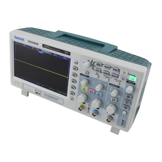
The figure below illustrates the front panel of the DSO5000 series digital oscilloscope. DSO5000... -
Page 22: Display Area
The oscilloscope works in auto mode and is acquiring waveforms in the absence of triggers. The oscilloscope is acquiring and displaying waveform data continuously in scan mode. ● The oscilloscope has stopped acquiring waveform data. The oscilloscope has finished a single sequence acquisition. DSO5000 Series Digital Storage Oscilloscope User Manual... -
Page 23: Xy Format
The XY format is used to analyze phase differences, such as those represented by Lissajous patterns. The format plots the voltage on CH1 against the voltage on CH2, where CH1 is the horizontal axis and CH2 is the vertical axis. The oscilloscope uses the untriggered Normal DSO5000 Series Digital Storage Oscilloscope User Manual... -
Page 24: Horizontal Controls
1. HORIZONTAL POSITION Knob: Used to control the trigger position against the screen center. Push this button to reset the trigger point back to the screen center. AN: Used to set the horizontal position as zero. 2. Each option in HORIZ MENU is described as follows. DSO5000 Series Digital Storage Oscilloscope User Manual... - Page 25 In the expanded window will display corresponding waveforms until it stops once reaching the rightmost side of the major scan window Single-window Mode Dual-window Mode (Full Screen) DSO5000 Series Digital Storage Oscilloscope User Manual...
-
Page 26: Scan Mode Display (Roll Mode)
5.2.1Scan Mode Display (Roll Mode) With the SEC/DIV control set to 80ms/div or slower and the trigger mode set to Auto, the oscilloscope works in the scan acquisition mode. In this mode, the waveform display is updated DSO5000 Series Digital Storage Oscilloscope User Manual... -
Page 27: Vertical Controls
HF components. VOLTS/DIV Coarse Selects the resolution of the VOLTS/DIV knob. Fine Coarse defines a 1-2-5 sequence. Fine changes the resolution to small steps between the Coarse settings. DSO5000 Series Digital Storage Oscilloscope User Manual... - Page 28 Three types of window available for selection: Hanning, Flattop, Rectangular. Zoom: Use the FFT Zoom button to adjust the window size. Scale: x1, x2, x5, x10. Note: All selected menus are highlighted in orange. DSO5000 Series Digital Storage Oscilloscope User Manual...
-
Page 29: Math Fft
6. If possible, set the oscilloscope to display multiple signal cycles. If you turn the SEC/DIV knob to select a faster setting (fewer cycles), the FFT spectrum will display a larger frequency range and reduce the possibility of FFT aliasing. DSO5000 Series Digital Storage Oscilloscope User Manual... -
Page 30: Displaying Fft Spectrum
Select a type of the FFT window. For more Rectangular information, refer to Section 5.3.1.3. FFT Zoom X1, X2, X5, X10 Change the horizontal magnification of the FFT display. For detailed information, refer to Section 5.3.1. DSO5000 Series Digital Storage Oscilloscope User Manual... -
Page 31: Selecting Fft Window
If the number of cycles is nonintegral, the YT waveform starts and ends at different amplitudes and transitions between the start and end points will cause discontinuities in the signal that introduces high-frequency transients. DSO5000 Series Digital Storage Oscilloscope User Manual... - Page 32 Window Measurement Characteristics Hanning Periodic Waveform Better frequency, poorer amplitude accuracy than Flattop Flattop Periodic Waveform Better amplitude, poorer frequency accuracy than Hanning Rectangular Pulse or Transient Special-purpose window applicable to discontinuous DSO5000 Series Digital Storage Oscilloscope User Manual...
-
Page 33: Fft Aliasing
That is, the axis for horizontal magnification is the center graticule line. Turn the Horizontal Position knob clockwise to move the FFT spectrum to the right. Push the SET TO ZERO button to position the center spectrum at the center of the graticule. DSO5000 Series Digital Storage Oscilloscope User Manual... -
Page 34: Using Cursors To Measure Fft Spectrum
The trigger can be defined through the Trigger Menu and front-panel controls. There are six types of trigger: Edge, Video, Pulse Width, Swap, Slope and Overtime. Refer to the following tables to find a different set of options for each type of trigger. DSO5000 Series Digital Storage Oscilloscope User Manual... - Page 35 Used to complete an acquisition regardless of an adequate trigger signal. This button becomes useless if the acquisition is already stopped. 4. TRIG MENU Push this button to display trigger menus. The edge trigger is in common use. See the table below for details. DSO5000 Series Digital Storage Oscilloscope User Manual...
- Page 36 NOTE: Trigger coupling only affects the signal passed through the trigger system. It does not affect the bandwidth or coupling of the signal displayed on the screen. Video Trigger Options Settings Comments Video With Video highlighted, an NTSC, PAL or SECAM DSO5000 Series Digital Storage Oscilloscope User Manual...
- Page 37 Select to trigger on positive or negative pulses. Negative Mode Auto Select the type of trigger. The Normal mode is best for Normal most pulse width trigger applications. Coupling Select the components of the trigger signal applied to the DSO5000 Series Digital Storage Oscilloscope User Manual...
- Page 38 Falling Mode Auto Select the type of trigger. The Normal mode is best for Normal most pulse width trigger applications. Coupling Selects the components of the trigger signal applied to the trigger circuitry. DSO5000 Series Digital Storage Oscilloscope User Manual...
- Page 39 Push F3 or F4 to select the components of the trigger signal applied to the trigger circuitry. HF Reject LF Reject Type Video Polarity Normal Inverted Standard NTSC PAL/SECAM Sync All Lines Select by F4, F5. Line Number Odd Field Even Field All Fields DSO5000 Series Digital Storage Oscilloscope User Manual...
- Page 40 This is called Overtime Trigger. Options Settings Comments Type Source Select the trigger source. Polarity Positive Select to trigger on positive or negative pulses. Negative DSO5000 Series Digital Storage Oscilloscope User Manual...
-
Page 41: Menu And Option Buttons
As shown below, these six buttons at the top of the front panel are used mainly to recall relative setup menus. SAVE/RECALL: Displays the Save/Recall menu for setups and waveforms. MEASURE: Displays the Measure menu. ACQUIRE: Displays the Acquire menu. DSO5000 Series Digital Storage Oscilloscope User Manual... -
Page 42: Save/Recall
Complete the saving operation. Recall Recall the oscilloscope settings stored in the location selected in the Setup field. Push the Default Setup button to initialize the oscilloscope to a known setup. See below for waveform menus. DSO5000 Series Digital Storage Oscilloscope User Manual... -
Page 43: Measure
Rise Time Measure the time between 10% and 90% of the first rising edge of the waveform. Fall Time Measure the time between 90% and 10% of the first falling edge of the waveform. DSO5000 Series Digital Storage Oscilloscope User Manual... -
Page 44: Acquire
‘ON’ (displayed) state to facilitate the measurement. The automatic measurement can not be performed on reference or math waveforms, or in XY or Scan mode. 5.5.3ACQUIRE Push the ACQUIRE button to set the acquisition parameter. DSO5000 Series Digital Storage Oscilloscope User Manual... - Page 45 Average: Use this mode to reduce random or uncorrelated noise in the signal to be displayed. Acquire data in Normal mode and then average a great number of waveforms. Choose the number of acquisitions (4, 16, 64 or 128) to average for the waveform. DSO5000 Series Digital Storage Oscilloscope User Manual...
-
Page 46: Utility
Hantek_1, Hantek_2 are generated. Self Press this option and the Self Calibration dialog pops up. Press F6 to perform Calibration the self calibration. Press F4 to cancel. Advance Buzzer and time setups DSO5000 Series Digital Storage Oscilloscope User Manual... - Page 47 (delta) between the cursors. Moving Cursors: Press the key near Select Cursor to select a cursor and turn V0 to move it. Cursors can be moved only when the Cursor Menu is displayed. DSO5000 Series Digital Storage Oscilloscope User Manual...
- Page 48 Press F5 to select this option. Turn the multi- functional knob to adjust. Next Page Grid Dotted line only displays horizontal vertical Real line coordinates at the center graticule on the screen. DSO5000 Series Digital Storage Oscilloscope User Manual...
-
Page 49: Cursor
Set to Vectors for an FFT spectrum; otherwise, unchanged Horizontal Position Adjusted SEC/DIV Adjusted Trigger Coupling Adjusted to DC, Noise Reject or HF Reject Trigger Holdoff Minimum Trigger Level Set to 50% Trigger Mode Auto DSO5000 Series Digital Storage Oscilloscope User Manual... - Page 50 Display multiple cycles that have appropriate vertical and horizontal scales. Single-cycle Square Set the horizontal scale to display about one cycle of the waveform. The oscilloscope displays Min, Mean and Positive Width automatic measurements. Rising Edge Display the rising edge. DSO5000 Series Digital Storage Oscilloscope User Manual...
-
Page 51: Default Setup
Vectors Persist Format Horizontal Window Mode Single-window Trigger Knob Level Position 0.00s SEC/DIV 200μs Math Operation — Source CH1-CH2 Position 0div Vertical Scale 20dB FFT Operation Source Window Hanning FFT Zoom Measure Source DSO5000 Series Digital Storage Oscilloscope User Manual... - Page 52 Mode Auto Coupling Level 0.00v Trigger (OT) Source Polarity Positive Mode Auto Time 20ns Vertical System, Coupling All Channels Bandwidth Limit Unlimited VOLTS/DIV Coarse Probe Voltage Voltage Probe Attenuation Invert Position 0.00div (0.00V) DSO5000 Series Digital Storage Oscilloscope User Manual...
-
Page 53: Multi-Functional Knobs And Buttons
‘next page’, ‘previous page’, and ‘press F6 to confirm’ appearing when you push Self Calibration option. 5.8 Signal Connectors See the figure below to find the three signals connectors and a pair of metal electrodes at the bottom of the oscilloscope panel. DSO5000 Series Digital Storage Oscilloscope User Manual... - Page 54 The probe compensation ground and BNC shields connect to earth ground and are considered to be ground terminals. To avoid damages, do not connect a voltage source to any of these ground terminals. DSO5000 Series Digital Storage Oscilloscope User Manual...
-
Page 55: Example 1: Taking Simple Measurements
Follow the steps below. Set the switch on the oscilloscope probe to 10X; Push the CH1 MENU button and set the Probe option attenuation to 10X; DSO5000 Series Digital Storage Oscilloscope User Manual... - Page 56 Repeat Step 2 and Step 3. Then select other measure items. Totally 8 measure items can be displayed. Note: All readouts change with the measured signals. The figure below shows three measure items as an example. The boxes under them display the measurements in large fonts. DSO5000 Series Digital Storage Oscilloscope User Manual...
-
Page 57: Example 2: Taking Cursor Measurements
Put Cursor S on the highest peak of the ring. 10. Put Cursor E on the lowest point of the ring. The amplitude of the ring will be displayed at Delta. See figures below for better understanding. DSO5000 Series Digital Storage Oscilloscope User Manual... - Page 58 Place Cursor S on the rising edge of the pulse and Cursor E on the falling edge. Thus at Delta displays the measured time and at Cursor S and Cursor E displays the time relative to the trigger. See the figure below for better understanding. DSO5000 Series Digital Storage Oscilloscope User Manual...
- Page 59 Select Cursor E and turn V0 to place it at the 90% level of the waveform. 10. The Delta readout in the Cursor Menu is the rise time of the pulse. See the figure below for better understanding. DSO5000 Series Digital Storage Oscilloscope User Manual...
-
Page 60: Noise
Press the ACQUIRE button to see the Acquire menu. Push the Type option button and select Real Time. Push the Peak Detect option button. If necessary, push the DISPLAY button and set the Contrast option to view the noise more DSO5000 Series Digital Storage Oscilloscope User Manual... - Page 61 Push the Averages option button and adjust the number of running averages to watch the change in the waveform display. Note: Averaging reduces random noise and let you view the signal details more easily. See the figure below for better understanding DSO5000 Series Digital Storage Oscilloscope User Manual...
-
Page 62: Example 4: Capturing Single-Shot Signal
For example, you need to measure the change in a phase across a circuit network. Connect the oscilloscope with circuitry and view the input and output of the circuit in XY mode. Follow the steps below. DSO5000 Series Digital Storage Oscilloscope User Manual... - Page 63 (π/2~π) or (π-3π/2). See the figure below for better understanding. Signal Horizontal Centering DSO5000 Series Digital Storage Oscilloscope User Manual...
-
Page 64: Example 6: Triggering On Pulse Width
10. If the When option is set to >, < or ≠ and there appear any aberrant pulses that meet the specified condition, the oscilloscope will trigger. For example, the signal contains such aberrant pulses as shown below, you may select ‘≠’ or ‘<’ to trigger on the pulse. DSO5000 Series Digital Storage Oscilloscope User Manual... -
Page 65: Example 7: Triggering On Video Signal
The figure below shows a stable signal triggering on a video field. Triggering on Video Lines To trigger on the video lines, follow the steps below. Push the TRIG MENU button to see the Trigger menu. DSO5000 Series Digital Storage Oscilloscope User Manual... -
Page 66: Signal
Click the ‘Next Page’ button and select Vertical. Turn the V0 knob to adjust V1 and V2 to proper locations. Select the When option button and set it to ‘=’. Select ‘Time’ and turn V0 to adjust the time until you get a stable display of waveforms. See DSO5000 Series Digital Storage Oscilloscope User Manual... -
Page 67: Signal
Turn V0 to adjust the line number (NTSC: 0-525 lines). Turn the horizontal SEC/DIV and the vertical VOLTS/DIV knobs to display on the screen a complete video signal triggering on a video line. See the figure below. DSO5000 Series Digital Storage Oscilloscope User Manual... -
Page 68: Waveforms
In addition, the oscilloscope also supports the - and FFT functions. For a detailed analysis on FFT, refer to Chapter 5.3.1 Math FFT. Note: You should compensate both probes before performing the math operation; DSO5000 Series Digital Storage Oscilloscope User Manual... -
Page 69: Example 11: Measuring Data Propagation Delay
6.11 Example 11: Measuring Data Propagation Delay When you doubt that there appear instabilities in a serial data propagation control circuit, you can set the oscilloscope to measure the propagation delay between the enable signal and the transfer DSO5000 Series Digital Storage Oscilloscope User Manual... - Page 70 Select Cursor S and turn V0 to place it on the active edge of the enable signal. Select Cursor E and turn V0 to place it on the data output transition (See the figure below). 10. Read the data propagation delay in the Delta readout. DATA DSO5000 Series Digital Storage Oscilloscope User Manual...
- Page 71 Application Examples DATA DSO5000 Series Digital Storage Oscilloscope User Manual...
-
Page 72: Problem Settlement
6) In addition, you may press the Auto Measure button to perform an automatic detection of signals at first. Contact HANTEK Technical Support department in time if there is still no display of waveforms. 3. If the waveform of the input signal is distorted seriously, follow these steps: 1)... -
Page 73: Technical Specifications
Chapter 8 Specifications 8.1 Technical Specifications All specifications herein mentioned apply to the DSO5000 series oscilloscopes. Before checking an oscilloscope from HANTEK to see if it complies with these specifications, make sure it meets the following conditions: The oscilloscope must have been operating continuously for twenty minutes under the specified operating temperature. - Page 74 Delta volts between any two averages of ≥16 Average Acquisition Mode waveforms acquired under same setup and ambient conditions Note: Bandwidth reduced to 6MHz when using a 1X probe. Trigger Trigger Sensitivity Coupling Sensitivity DSO5000 Series Digital Storage Oscilloscope User Manual...
- Page 75 Peak-to-peak amplitude of 2 divisions 400mV EXT/5 Signal Formats and Supports NTSC, PAL and SECAM Field Rates, Video broadcast systems for any field or Trigger Type any line Holdoff Range 100ns to 10s DSO5000 Series Digital Storage Oscilloscope User Manual...
- Page 76 The Frequency Counter measures trigger source at all times, including when the oscilloscope acquisition pauses due to changes in the run status, or acquisition of a single shot event has completed. Pulse Width Trigger mode: The oscilloscope counts pulses of significant DSO5000 Series Digital Storage Oscilloscope User Manual...
- Page 77 Voltage difference between cursors: △V Time difference between cursors: △T Reciprocal of △T in Hertz (1/ΔT) Automatic Frequency, Period, Mean, Peak-to-peak, Cycle RMS, Minimum, Maximum, Measurements Rise Time, Fall Time, Positive Width, Negative Width DSO5000 Series Digital Storage Oscilloscope User Manual...
-
Page 78: Accessories
2.08Kg accessories Packing Length 385mm Width 200mm Height 245mm Gross Weight inclusive of all accessories 约 2.5Kg 8.2 Accessories All the following accessories are available by contacting your local HANTEK distributor. DSO5000 Series Digital Storage Oscilloscope User Manual... - Page 79 (rated 300Vrms CAT II) when the switch is in the X10 position. Each probe consists of all necessary fittings. A quick guide of the DSO5000 series oscilloscopes. It gives a description mainly on functions and operating basis of these oscilloscopes.
- Page 80 Chapter 9 Services and Support Thank you for choosing HANTEK. Please contact us through the following ways should you have any inquiry regarding our products. We shall do our best to help you. Contact your local HANTEK distributor; 1. Contact your local HANTEK field office;...
-
Page 81: Chapter 10
General Care and Cleaning Chapter 10 General Care and Cleaning 10.1 General Care Do not put or leave the device in a place where the LCD display will be exposed to direct sunlight for long periods of time. Note: To avoid damage to the oscilloscope or probes, do not expose them to sprays, liquids, or solvents. -
Page 82: Appendix A Harmful And Poisonous Substances Or Elements
Harmful and Poisonous Substances or Elements Appendix A Harmful and Poisonous Substances or Elements Harmful and poisonous substances or elements Component Cr(Vi) PBDE Shell and Chassis Display Module Circuit Board Power Supply Electric Wire and Cable Assembly Connector Fastener and Installed Hardware Other Accessories (including probes) Others... -
Page 83: Appendix B Index
Harmful and Poisonous Substances or Elements Appendix B Index Search by alphabetical order AC coupling Factory setup ACQUIRE button FFT aliasing Acquisition mode FFT Window Amplitude cursor FFT Zoom Application examples Field synchronization Automatic measurement Fine resolution AUTOSET Force trigger AUTOSET button Frequency counter Autoset function... - Page 84 Harmful and Poisonous Substances or Elements MATH MENU button SEC/DIV knob MEASURE button Self calibration Measure FFT spectrum SET TO 50% button Measurement cursor Simple measurement Mechanical Sine wave Mechanical shock SINGLE SEQ button Menu hiding Slope Multi-functional knob Slope trigger Software installation CD Square wave Negative pulse...
- Page 85 Harmful and Poisonous Substances or Elements XY format...
Need help?
Do you have a question about the DSO5000 Series and is the answer not in the manual?
Questions and answers