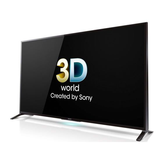
Version up procedure, az1bd/h/l chassis (42 pages)
Summary of Contents for Sony KDL-60W855B
Page 1
Self Diagnosis Supported model HISTORY INFORMATION FOR THE FOLLOWING MANUAL: REPAIR MANUAL RB2G Chassis Segment: HE MODEL COMMANDER DESTINATION KDL-60W855B RM-YD099/RMF-YD003 BRAZIL KDL-70W855B RM-YD099 BRAZIL KDL-60W855B Version Date Subject 02/07/2014 Original Manual Release Date. LCD Digital Color TV 9-883-570-01...
For safety reasons, component level repair of the Power Supply Boards and/or the Inverter Boards is prohibited. CAUTION ABOUT THE LITHIUM BATTERY!! Replace only with the same or equivalent type. Danger of explosion mayoccur if battery is replaced incorrectly. Exposed battery should not be incontact with water. KDL-60W855B/70W855B...
Page 4
2 VAC range are suitable. (see Figure A) To Exposed Metal Figure B. Checking for earth ground. Parts on Set Voltmeter 0.15 µF (0.75V) Earth Ground Figure A. Use an AC voltmeter to check AC leakage. KDL-60W855B/70W855B...
SECTION 1 - SPECIFICATIONS AND LAYOUTS SPECIFICATIONS Sistema Nome do modelo KDL-70W855B KDL-60W855B Sistema de televisão Analógico: NTSC/PAL-M/PAL-N Digital: SBTVD Alimentação e outros Cobertura de canais VHF: 2-13 Requisitos de alimentação 110-220V CA, 60Hz UHF: 14-69 Consumo de em uso...
Total operation time by hour (MAX:65535) Total operation time by hour (MAX:65535) *Format of Error History = YYMMDDhhmmss example 120123132522= Jan 23, 2012 13:25:22 (1:25:22PM) NOTE: date and time must be set for this to work SAMPLE SELF CHECK DIAGNOSIS PAGE KDL-60W855B/70W855B...
▲ ▲ LCD PANEL AUDIO/ BACK- SOFT- EMI- Problem POWER TCON TEMP POWER LIGHT WARE TTER *NOTE: REFER TO LCD PANELS SERVICE MANUAL IN REFERENCE LIBRARY DATABASE FOR CORRECT REPLACEMENT PARTS BASED ON SERIAL NUMBER. KDL-60W855B/70W855B...
CAMERA LVDS TCON TUNER BOARD LED BACKLIGHTS VIDEO 1 CVBS VIDEO 2 CVBS/COMP TUNER SWITCH DEMODULATOR TUNER UNIT ADC / DACAMP LOCAL DIMMING TUNER CABLE ANTENNA SMART CORE IR RX WIFI SWITCH UNIT HSC2 POWER SUPPLY AC IN BOARD KDL-60W855B/70W855B...
See Stanby High (3.3V) Power Supply Is Standby LED Power Supply LED Blinking appears Board* blinking? Board* Flowchart momentarily? Power Supply Main Board* Board* *For Part Number information, refer to “Section 4 - Exploded View/Part Number Information” on page KDL-60W855B/70W855B...
Tuner Board* Main Board* See Triage Chart HEM3 Board After a while Check ventilation Imediately TCON Power Supply Main Board* LCD Panel* (LCD Panel)* Board* *For Part Number information, refer to “Section 4 - Exploded View/Part Number Information” on page KDL-60W855B/70W855B...
Main Board* (LCD Panel) Any horizontal LCD Panel* lines? Any single or LCD Panel* isolated vertical lines? More than 1 TCON* vertical band? (LCD Panel) *For Part Number information, refer to “Section 4 - Exploded View/Part Number Information” on page KDL-60W855B/70W855B...
Active Double images Active 3D become one/ 3D Glasses/ become one? Glasses Remote works One Touch Remote Control? Bluetooth 3D OK Board* *For Part Number information, refer to “Section 4 - Exploded View/Part Number Information” on page KDL-60W855B/70W855B...
2. Place TV face down on a soft and flat surface to remove all screws and detach the left and right Stand. 6. Firmly lift the Rear Cover on the shown areas to detach. 3. Remove 1 screw from AC Cover and disconnect the AC Power Cord. HOLD KDL-60W855B/70W855B...
After ALL repairs UPDATE the SOFTWARE to the latest version. The Main Board used in these models is available for repair. For Part Instructions are included with the Software package on the Sony Number information refer to Section 4 - Exploded View/Part Number website.
Page 18
15. Locate the Serial Number for the TV on the side of the Rear Cover. 10. Press until the correct destination of the TV displays. (Use the table below for reference). MODEL NO Model Name Destination Data Value KDL-60W855B KDL-60W855B BRAZIL SBTVD-T_BASE SERIAL NO KDL-70W855B BRAZIL SBTVD-T_BASE 2000001 11.
Page 19
1. Replace MAIN BOARD (and TUNER BOARD) 22. Press until STD option displays. 2. Replace TUNER BOARD only DIGITAL SERVICE 002 MODEL 006 VAR_TYPE 23. Press then to save the changes. MUTE DIGITAL SERVICE 002 MODEL 006 VAR_TYPE WRITE KDL-60W855B/70W855B...
Page 20
“NG: WRONG COMBINATION OF MAIN BOARD AND TUNER WRITE BOARD” will display. 29. Press then to save the changes. RETURN MUTE DIGITAL (MODEL) SERVICE Board Check 1. Replace MAIN BOARD (and TUNER BOARD) 2. Replace TUNER BOARD only WRITE KDL-60W855B/70W855B...
After ALL repairs UPDATE the SOFTWARE to the latest version. 003 TU_DEMOD --------------------- --------------------- --------------------- 00 004 VLED --------------------- --------------------- --------------------- 00 Instructions are included with the Software package on the Sony 004 LD_ERR --------------------- --------------------- --------------------- 00 website. 005 HFR_ERR...
Wireless LAN Card. Wireless Wireless LAN Card LAN Card Smart Core Block Smart Core Block BT Module BT Module 4. Pull Bottom Cover on the direction shown to detach from Top Cover. Top Cover Top Cover Bottom Cover Bottom Cover KDL-60W855B/70W855B...
(See Appendix A) Replace only with part number specified. REF. NO. PART NO. DESCRIPTION A-2033-095-A STAND RIGHT (60) (KDL-60W855B ONLY) A-2033-093-A STAND RIGHT (70) (KDL-70W855B ONLY) A-2033-094-A STAND LEFT (60) (KDL-60W855B ONLY) A-2033-092-A...
NOTE: The components identified by a red outline and a mark contain confidential NOTE: The components identified by shading and KDL-60W855B information. Specific instructions must be adhered to whenever these components are mark are critical for safety. repaired and/or replaced. (See Appendix A) Replace only with part number specified.
LABEL, SIDE TERMINAL ORDER THIS PART WHEN REPLACING THE REAR COVER. A-1997-422-A BRACKET SP (LEFT) 1-859-005-11 SPEAKER BOX (LEFT) Smart Core Smart Core Block Block 4-484-096-01 BRACKET, VESA (S) A-1997-423-A BRACKET SP (RIGHT) 1-859-005-21 SPEAKER BOX (RIGHT) 4-484-098-01 BRACKET, VESA (L) KDL-60W855B/70W855B...
Page 26
NOTE: The components identified by a red outline and a mark contain confidential NOTE: The components identified by shading and KDL-60W855B information. Specific instructions must be adhered to whenever these components are mark are critical for safety. repaired and/or replaced. (See Appendix A) Replace only with part number specified.
Page 27
BAX BOARD, COMPLETE AFTER REPLACING THE MAIN BOARD, YOU MUST UPDATE THE SOFTWARE TO THE LATEST VERSION. 4-480-397-11 BRACKET, SIDE 1-798-510-21 SWITCH UNIT 4-480-122-01 HOLDER, SIDE SW A-1997-420-A PANEL SIDE (LEFT) REINSTALL THIS PART WHEN REPLACING THE LCD PANEL. KDL-60W855B/70W855B...
Page 28
NOTE: The components identified by a red outline and a mark contain confidential NOTE: The components identified by shading and KDL-60W855B information. Specific instructions must be adhered to whenever these components are mark are critical for safety. repaired and/or replaced. (See Appendix A) Replace only with part number specified.
Page 29
LCD PANEL FOR LCD PANEL AND TCON BOARD PART NUMBER INFORMATION REFER TO THE LCD PANELS SERVICE MANUAL. 4-440-057-01 SHEET, THERMAL (AYU2) ORDER THIS PART WHEN REPLACING THE MAIN BOARD. *Reinstall Main Board Plate when replacing the LCD Panel. KDL-60W855B/70W855B...
(See Appendix A) Replace only with part number specified. REF. NO. PART NO. DESCRIPTION 4-474-894-01 BACK COVER 1-492-760-21 BT MODULE 1-458-723-21 WIRELESS LAN CARD 4-474-893-01 FRONT COVER 4-480-410-01 TOP COVER A-1969-163-A HSC2 BOARD, MOUNTED A-1994-033-A BOTTOM CASE KDL-60W855B/70W855B...
NOTE: The components identified by shading and CONNECTORS information. Specific instructions must be adhered to whenever these components are mark are critical for safety. repaired and/or replaced. (See Appendix A) Replace only with part number specified. KDL-60W855B KDL-70W855B REF. NO. PART NO. DESCRIPTION REF. NO.
(See Appendix A) Replace only with part number specified. DESCRIPTION KDL-60W855B/70W855B 2-580-639-01 SCREW, +BVTP 4X12 TYPE2 IT-3 Rear Cover (9), Cover Under (1) Smart Core Block (2) Main Board (6), Power Supply Board (5), Switch Unit Holder (1),...
CASE, BATTERY (3D GLASSES) (SCREWS TO ATTACH TABLE TOP STAND TO LCD TV) 4-460-761-01 PAD, NOSE (3D GLASSES) For product protection and safety reasons, Sony strongly recommends 4-485-653-01 CLAMPER, CABLE (M) that you use the screws provided with the TV.
APPENDIX A: ENCRYPTION KEY COMPONENTS Encryption key components developed by Sony Corporation contain confidential information and shall be handled under the non-disclosure obligations provided in the applicable agreement with Sony Corporation (and/or its subsidiary). As part of this agreement specific instructions must be adhered to whenever a Circuit Board containing encryption key components is repaired and/or replaced pursuant to the following: In the service manual the Circuit Board(s) containing encryption key components shall be identified with a red outline and a .
Need help?
Do you have a question about the KDL-60W855B and is the answer not in the manual?
Questions and answers