Table of Contents
Advertisement
Available languages
Available languages
Harbor Breeze® is a registered trademark
of LF, LLC. All Rights Reserved.
ATTACH YOUR RECEIPT HERE
Serial Number _________________________
Questions, problems, missing parts? Before returning to your retailer, call our customer
service department at 1-800-643-0067, 8 a.m. - 6 p.m., EST, Monday - Thursday, 8 a.m. - 5 p.m.,
EST, Friday.
EB13349
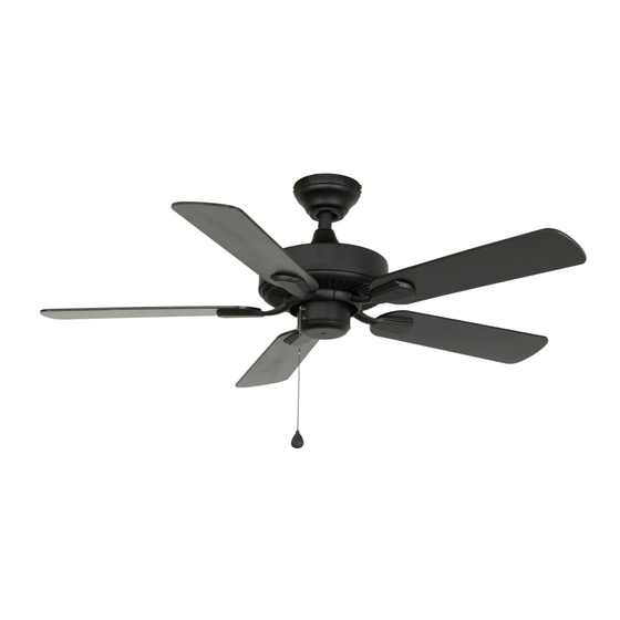
42 IN CLASSIC STYLE
Purchase Date _________________________
Lowes.com/harborbreeze
1
ITEM #0451796, 0451795
CEILING FAN
MODEL #40113, 40114
Español p. 22
LISTED FOR
WET LOCATION
Advertisement
Chapters
Table of Contents

Subscribe to Our Youtube Channel
Related Manuals for Harbor Breeze 40113


Summary of Contents for Harbor Breeze 40113
- Page 1 ITEM #0451796, 0451795 42 IN CLASSIC STYLE CEILING FAN MODEL #40113, 40114 Harbor Breeze® is a registered trademark of LF, LLC. All Rights Reserved. Español p. 22 LISTED FOR ATTACH YOUR RECEIPT HERE WET LOCATION Serial Number _________________________ Purchase Date _________________________ Questions, problems, missing parts? Before returning to your retailer, call our customer service department at 1-800-643-0067, 8 a.m.
-
Page 2: Table Of Contents
TABLE OF CONTENTS Package Contents ..............3 Hardware Contents . -
Page 3: Package Contents
PACKAGE CONTENTS PART DESCRIPTION QUANTITY Downrod Canopy (preassembled to Mounting Bracket (C)) Mounting Bracket Yoke Cover Motor Assembly Switch Housing (preassembled to Motor Assembly (E)) Switch Housing Cap (preassembled to Switch Housing (F)) Blade Arm Blade Canopy Cover (preassembled to Canopy (B)) Lowes.com/harborbreeze... -
Page 4: Hardware Contents
HARDWARE CONTENTS Motor Screw Wire Pull Chain Downrod Clip Downrod Pin Qty. 10 Connector Extension Qty. 1 Qty. 1 (preassembled to Qty. 3 + 1 extra Qty. 1 (preassembled to (preassembled to Motor Assembly (E)) Downrod (A)) Downrod (A)) + 1 extra Motor Housing Set Closemount Mounting Bracket... -
Page 5: Safety Information
SAFETY INFORMATION Please read and understand this entire manual before attempting to assemble, operate or install the product. • Before you begin installing the fan, disconnect the power by removing fuses or turning off the circuit breakers. • Make sure that all electrical connections comply with local codes, ordinances, the National Electrical Code, and ANSI/NFPA 70-199. Hire a qualified electrician or consult a do-it-yourself wiring handbook if you are unfamiliar with installing electrical wiring. -
Page 6: Preparation
SAFETY INFORMATION CAUTION: Read all instructions and safety information before installing your new fan. Review the accompanying assembly diagrams. CAUTION: Be sure the outlet box is properly grounded or that a ground (green or bare) wire is present. CAUTION: Carefully check all screws, bolts, and nuts on the fan motor assembly to ensure they are secured. -
Page 7: Initial Installation
INITIAL INSTALLATION 1. Turn off the circuit breakers and the wall switch to the fan supply line leads. DANGER: Failure to disconnect the power supply prior to installation may result in serious injury or death. 2. Determine the mounting method to use. Helpful Hint: Downrod mounting is best suited for ceilings 8 ft. - Page 8 INITIAL INSTALLATION 4. Remove the two mounting bracket screws (HH) from the round holes of the canopy (B). Set aside for later use. Detach mounting bracket (C) from canopy (B). Hardware Used Mounting Bracket Screw Feed black, blue and white wires up from the plug on the mounting bracket (C) up through the hole in the top.
-
Page 9: Standard Or Angle Mounting Instructions
STANDARD OR ANGLE MOUNTING INSTRUCTIONS WARNING: To reduce the risk of fire, electrical shock, or personal injury, wire connectors provided with this fan are designed to accept only one 12-gauge house wire and two lead wires from the fan. If your house wire is larger than 12 gauges and there is more than one house wire to connect to the two fan lead wires, consult an electrician for the proper size wire connectors to use. - Page 10 STANDARD OR ANGLE MOUNTING INSTRUCTIONS 4. Feed green/bare (ground) supply wire down through the hole in the top of the mounting bracket (C). Secure the mounting bracket (C) to the outlet box using screws and washers provided with the outlet box. Remove the downrod clip (DD) and downrod pin (EE) from the downrod (A).
- Page 11 STANDARD OR ANGLE MOUNTING INSTRUCTIONS Slide the downrod (A) into the yoke of the motor assembly (E), align the holes, and re-install the downrod clip (DD) and downrod pin (EE). Then tighten the motor housing set screws (FF). Hardware Used Downrod Clip Downrod Pin Motor Housing...
- Page 12 CLOSEMOUNT INSTRUCTION WARNING: To reduce the risk of fire, electrical shock, or personal injury, wire connectors provided with this fan are designed to accept only one 12-gauge house wire and two lead wires from the fan. If your house wire is larger than 12 gauges and there is more than one house wire to connect to the two fan lead wires, consult an electrician for the proper size wire connectors to use.
-
Page 13: Closemount Instructions
CLOSEMOUNT INSTRUCTIONS Secure the mounting bracket (C) to the outlet box using screws and washers provided with the outlet box. Remove the canopy cover (J) from the bottom of the canopy (B). Helpful Hint: Closemount-style mounting is more suitable for ceilings lower than 8 ft. high. The downrod (A) and canopy cover (J) are not used in this type of installation. - Page 14 CLOSEMOUNT INSTRUCTIONS Raise the fan and place the canopy (B) on the hook on the mounting bracket (C). Lowes.com/harborbreeze...
-
Page 15: Final Installation
FINAL INSTALLATION Note: Downrod (A) is shown/referenced, but instructions are applicable to both standard and closemount-style installations. Wrap the wire harness coming from the downrod (A) around the hooks on the back of the mounting bracket (C). Note: Extra wire harness length accommodates longer downrods (sold separately). - Page 16 FINAL INSTALLATION Secure the canopy (B) with mounting bracket screws (HH) previously removed (Step 4, page 8). Tighten all mounting bracket screws (HH) securely. Hardware Used Mounting Bracket Screw Align blade arm (H) studs with their corresponding holes in the blade (I) and then insert the blade screw (II), blade washer (JJ) and rubber washer (LL) to attach one blade arm (H) to a blade (I).
-
Page 17: Operating Instructions
FINAL INSTALLATION Attach the pull chain extension (CC) or custom pull chain extension (not included) to the fan pull chain. Hardware Used Pull Chain Extension OPERATING INSTRUCTIONS 1. The pull chain labeled FAN has four positions to control fan speed. One pull is HIGH, two is MEDIUM, three is LOW and four turns the fan OFF. -
Page 18: Care And Maintenance
CARE AND MAINTENANCE At least twice each year, lower the canopy to check the downrod assembly, and then tighten all screws on the fan. Clean the motor housing with only a soft brush or lint-free cloth to avoid scratching the finish. Clean the blades with a lint-free cloth. You may occasionally apply a light coat of furniture polish to wood blades for added protection. - Page 19 TROUBLESHOOTING PROBLEM POSSIBLE CAUSE CORRECTIVE ACTION 1. The blades and/or blade are 1. Check and tighten all screws that loose. hold the fan blades to the blade arms and the blade arms to the motor. 2. The blades are unbalanced. 2.
-
Page 20: Limited Lifetime Warranty
LIFETIME LIMITED WARRANTY The manufacturer warrants this fan to be free from defects in workmanship and materials present at time of shipment from the factory for a lifetime from the date of purchase by the original purchaser. The retailer also warrants that all other fan parts, excluding any glass or plexiglas blades, to be free from defects in workmanship and material at the time of shipment from the factory for a period of one year after the date of purchase by the original purchaser. -
Page 21: Replacement Parts List
#0451796 #0451795 Downrod 0451796-A 0451795-A Canopy 0451796-B 0451795-B Mounting Bracket 0451796-C 0451795-C Blade Arm 0451796-H 0451795-H Blade 0451796-I 0451795-I Hardware Kit 0451796-HW 0451795-HW Printed in China Harbor Breeze is a registered trademark of LF, LLC. All Rights Reserved. ® Lowes.com/harborbreeze... - Page 22 ARTÍCULO #0451796, 0451795 VENTILADOR DE TECHO CLASSIC STYLE DE 106,68 CM MODELO #40113, 40114 Harbor Breeze es una marca registrada de LF, LLC. ® Todos los derechos reservados. HOMOLOGADO PARA LUGARES ADJUNTE SU RECIBO AQUÍ HÚMEDOS Número de serie _________________________ Fecha de compra _________________________ ¿Preguntas, problemas, piezas faltantes? Antes de volver a la tienda, llame a nuestro...
- Page 23 ÍNDICE Contenido del paquete ............24 Aditamentos.
-
Page 24: Contenido Del Paquete
CONTENIDO DEL PAQUETE PIEZA DESCRIPCIÓN CANTIDAD Varilla Base (preensamblado en la abrazadera de montaje (C)) Abrazadera de montaje Cubierta de la horquilla Ensamble del motor Carcasa del interruptor (preensamblada en el ensamblaje del motor (E)) Tapa de la carcasa del interruptor (preensamblado en la tapa de la carcasa del interruptor (F)) Brazo del aspa Aspa... -
Page 25: Aditamentos
ADITAMENTOS Tornillo del motor Conector de Extensión para la Sujetador de la Pasador de Cant. 10 cables cadena de tiro varilla la varilla (preensamblado en la Cant. 3 Cant. 1 Cant. 1 Cant. 1 carcasa del motor [A]) y 1 adicional (preensamblado (preensamblado y 1 adicional... -
Page 26: Información De Seguridad
INFORMACIÓN DE SEGURIDAD Lea y comprenda completamente este manual antes de intentar ensamblar, usar o instalar el producto. • Antes de comenzar a instalar el ventilador, desconecte la alimentación eléctrica; para esto retire los fusibles o coloque el interruptor de circuito en la posición de apagado. •... -
Page 27: Preparación
INFORMACIÓN DE SEGURIDAD PRECAUCIÓN: Lea todas las instrucciones y la información de seguridad antes de instalar el nuevo ventilador. Revise los diagramas de ensamblaje adjuntos. PRECAUCIÓN: Asegúrese de que la caja de salida cuente con la puesta a tierra adecuada o de que haya un conductor (verde o desnudo) de tierra. -
Page 28: Instalación Inicial
INSTALACIÓN INICIAL 1. Gire las abrazaderas de circuito y el interruptor de pared hacia los conductores de la línea de suministro del ventilador. PELIGRO: Si no interrumpe el suministro de electricidad antes de la instalación, pueden producirse lesiones graves o la muerte. 2. - Page 29 INSTALACIÓN INICIAL 4. Retire los dos tornillos de la abrazadera de montaje (HH) de los orificios redondos de la base. Déjelos a un lado para usarlos posteriormente. Retire la abrazadera de montaje (C) de la base (B). Aditamentos utilizados Tornillo de la abrazadera de montaje 5.
-
Page 30: Instrucciones De Montaje En Ángulo Y Estándar
INSTRUCCIONES DE MONTAJE EN ÁNGULO Y ESTÁNDAR ADVERTENCIA: Para reducir el riesgo de incendios, descargas eléctricas o lesiones personales, los conectores de cables proporcionados con este ventilador están diseñados para soportar solo un cable de la casa de calibre 12 y dos cables conductores del ventilador. Si el cable de la casa es de un calibre superior a 12 o hay más de un cable de la casa para conectar los dos cables conductores del ventilador, pregúntele a un electricista cuál es el tamaño adecuado de los conectores de cables que debe utilizar. - Page 31 INSTRUCCIONES DE MONTAJE EN ÁNGULO Y ESTÁNDAR 4. Pase el conductor de suministro verde/desnudo (de puesta a tierra) por el orificio en la parte superior de la abrazadera de montaje (C). Asegure la abrazadera de montaje (C) a la caja de salida con los tornillos y las arandelas que incluye la caja de salida.
- Page 32 INSTRUCCIONES DE MONTAJE EN ÁNGULO Y ESTÁNDAR Deslice la varilla (A) por la horquilla del ensamblaje del motor (E), alinee los orificios y vuelva a instalar el sujetador (DD) y el pasador de la varilla (EE). Luego vuelva a apretar los tornillos de ajuste de la carcasa del motor (FF).
-
Page 33: Instrucciones Para Montaje Cerrado
INSTRUCCIONES PARA MONTAJE CERRADO ADVERTENCIA: Para reducir el riesgo de incendios, descargas eléctricas o lesiones personales, los conectores de cables proporcionados con este ventilador están diseñados para soportar solo un cable de la casa de calibre 12 y dos cables conductores del ventilador. Si el cable de la casa es de un calibre superior a 12 o hay más de un cable de la casa para conectar los dos cables conductores del ventilador, pregúntele a un electricista cuál es el tamaño adecuado de los conectores de cables que debe utilizar. - Page 34 INSTRUCCIONES PARA MONTAJE CERRADO Asegure la abrazadera de montaje (C) a la caja de salida con los tornillos y las arandelas que incluye la caja de salida. Retire la cubierta de la base (J) de la parte inferior de la base (B). Consejo útil: El estilo de montaje cerrado es más adecuado para los techos de menos de 2,44 m (8 pies) de alto.
- Page 35 INSTRUCCIONES PARA MONTAJE CERRADO Levante el ventilador y coloque la base (B) en el gancho de la abrazadera de montaje (C). Lowes.com/harborbreeze...
-
Page 36: Instalación Final
INSTALACIÓN FINAL Nota: Se hace referencia/se muestra la varilla (A), pero las instrucciones se aplican a las instalaciones estándar y a las de montaje cerrado. Envuelva el arnés de cableado que proviene de la varilla (A) alrededor de los ganchos en la parte posterior de la abrazadera de montaje (C). - Page 37 INSTALACIÓN FINAL Asegure la base (B) con los tornillos del soporte de montaje (HH) que retiró anteriormente. Apriete firmemente los cuatro tornillos del soporte de montaje (HH). Aditamentos utilizados Tornillo de la abrazadera de montaje Alinee los montantes del brazo del aspa (H) con los respectivos orificios en el aspa (I) y luego inserte el tornillo del aspa (II), la arandela del aspa (JJ) y la arandela de goma (LL) para fijar un brazo de aspa...
-
Page 38: Instrucciones De Funcionamiento
INSTALACIÓN FINAL Conecte la extension para la cadena de tiro (CC) o las extension para la cadena de tiro personalizadas (no incluidas) con la cadena de tiro del ventilador. Aditamentos utilizados Extensión para la cadena de tiro INSTRUCCIONES DE FUNCIONAMIENTO 1. -
Page 39: Cuidado Y Mantenimiento
CUIDADO Y MANTENIMIENTO Al menos dos veces al año, baje la base para revisar en ensamble de la varilla, y luego apriete todos los tornillos en el ventilador. Limpie la carcasa del motor solo con un cepillo suave o un paño sin pelusas para evitar rayar el acabado. - Page 40 SOLUCIÓN DE PROBLEMAS PROBLEMA CAUSA POSIBLE ACCIÓN CORRECTIVA 1. Una o varias aspas están 1. Revise y apriete todos los tornillos flojas. que sostienen las aspas del ventilador en los brazos de las aspas y en el motor. 2. Las aspas no están equilibradas.
-
Page 41: Garantía Limitada De Por Vida
GARANTÍA LIMITADA DE POR VIDA El fabricante garantiza que este ventilador no presenta defectos de mano de obra ni de materiales en el momento del transporte desde la fábrica durante un período de por vida a partir de la fecha de compra del comprador original. -
Page 42: Lista De Piezas De Repuesto
0451795-A Base 0451796-B 0451795-B Abrazadera de montaje 0451796-C 0451795-C Brazo del aspa 0451796-H 0451795-H Aspa 0451796-I 0451795-I Kit de aditamentos 0451796-HW 0451795-HW Impreso en China Harbor Breeze es una marca registrada de LF, LLC. ® Todos los derechos reservados. Lowes.com/harborbreeze...
Need help?
Do you have a question about the 40113 and is the answer not in the manual?
Questions and answers