Table of Contents
Advertisement
Available languages
Available languages
Harbor Breeze® is a registered trademark
of LF, LLC. All Rights Reserved.
ATTACH YOUR RECEIPT HERE
Serial Number _________________________
Questions, problems, missing parts? Before returning to your retailer, call our customer
service department at 1-800-643-0067, 8 a.m. - 6 p.m., EST, Monday - Thursday, 8 a.m. - 5 p.m.,
EST, Friday.
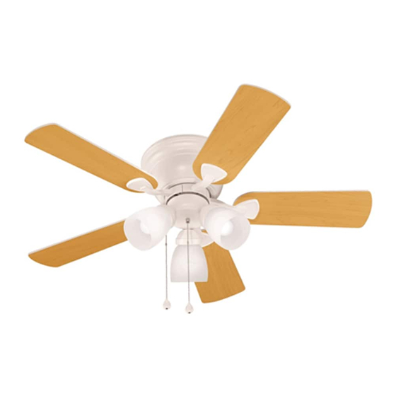
ITEM #0403515, 0403516, 0403514
42 IN. CENTREVILLE
Purchase Date _________________________
1
CEILING FAN
MODEL #40109, 40110, 40111
Español p. 24
Lowes.com/harborbreeze
Advertisement
Chapters
Table of Contents

Subscribe to Our Youtube Channel
Related Manuals for Harbor Breeze CENTREVILLE 40109


Summary of Contents for Harbor Breeze CENTREVILLE 40109
- Page 1 ITEM #0403515, 0403516, 0403514 42 IN. CENTREVILLE CEILING FAN MODEL #40109, 40110, 40111 Harbor Breeze® is a registered trademark of LF, LLC. All Rights Reserved. Español p. 24 ATTACH YOUR RECEIPT HERE Serial Number _________________________ Purchase Date _________________________ Questions, problems, missing parts? Before returning to your retailer, call our customer service department at 1-800-643-0067, 8 a.m.
-
Page 2: Table Of Contents
TABLE OF CONTENTS Package Contents ..............3 Hardware Contents . -
Page 3: Package Contents
PACKAGE CONTENTS PART DESCRIPTION Motor Housing Upper Mounting Bracket Extra Switch Housing Motor Assembly Light Kit Fitter Twist-On Glass Shade Blade Arm Blade Bulb Switch Housing Plate (preassembled to Motor Assembly (D)) Lower Mounting Bracket (preassembled to Motor Assembly (D)) Lowes.com/harborbreeze... -
Page 4: Hardware Contents
HARDWARE CONTENTS Blade Screw Fiber Blade Washer Wire Connector Pull Chain Extension Qty. 15 + 1 extra Qty. 15 + 1 extra Qty. 4 Qty. 2 Motor Screw Motor Housing Light Kit Screw Bracket Screw Qty. 10 + 1 extra Mounting Screw Qty. -
Page 5: Safety Information
SAFETY INFORMATION Please read and understand this entire manual before attempting to assemble, operate, or install the product. • Before you begin installing the fan, disconnect the power by removing fuses or turning off the circuit breakers. • Make sure that all electrical connections comply with local codes, ordinances, the National Electrical Code, and ANSI/NFPA 70-199. Hire a qualified electrician or consult a do-it-yourself wiring handbook if you are unfamiliar with installing electrical wiring. -
Page 6: Preparation
SAFETY INFORMATION CAUTION: Read all instructions and safety information before installing your new fan. Review the accompanying assembly diagrams. CAUTION: Be sure the outlet box is properly grounded or that a ground (green or bare) wire is present. CAUTION: Carefully check all screws, bolts, and nuts on the fan motor assembly to ensure that they are secured. -
Page 7: Initial Installation
INITIAL INSTALLATION 1. Turn off the circuit breakers and the wall switch to the fan supply line leads. DANGER: Failure to disconnect the power supply prior to installation may result in serious injury or death. 2. Check to make sure the blades (H) are at least 30 in. from any obstruction and at least 7 ft. above the floor. - Page 8 INITIAL INSTALLATION 4. Remove the motor screws (EE) from the motor (D) and save for later use. If there are plastic motor blocks installed, remove and discard them. Hardware Used Motor Screw x 10 5. Remove the bracket screws (HH) from underneath the lower mounting bracket (K).
- Page 9 INITIAL INSTALLATION 7. Reinstall the previously-removed bracket screws (HH) underneath the lower mounting bracket (K) and into the upper mounting bracket (B). Securely tighten the screws. Hardware Used Bracket Screw Lowes.com/harborbreeze...
-
Page 10: Wiring
WIRING WARNING: To reduce the risk of fire, electrical shock, or personal injury, wire connectors provided with this fan are designed to accept only one 12-gauge house wire and two lead wires from the fan. If your house wire is larger than 12 gauges and there is more than one house wire to connect to the two fan lead wires, consult an electrician for the proper size wire connectors to use. - Page 11 WIRING 1C. FAN AND LIGHT CONTROLLED BY TWO WALL SWITCHES: To control the fan and light with separate wall switches, connect the Black wire from BLACK (WALL SWITCH) 120 V Power the fan to the Black wire from the wall switch for the FROM BLACK (WALL SWITCH FOR LIGHT) CEILING...
- Page 12 WIRING 3. Turn the spliced/taped wires upward and gently push the wires and wire connectors (CC) into the outlet box. WARNING: Ensure that no bare wire or wire strands are visible after making connections. Place the Green and White wire connections on opposite sides of the outlet box from the Black and Blue (if applicable) wire connections.
-
Page 13: Final Installation
FINAL INSTALLATION 1. Temporarily lift the motor housing (A) to the mounting bracket (B) to determine which two motor housing mounting screws (FF) in the sides of the mounting bracket (B) align with the slotted holes in the top edge of the motor housing (A). Partially loosen the two motor housing mounting screws (FF) that align with the slotted holes. - Page 14 FINAL INSTALLATION 3. Partially insert three blade screws (AA) along with three fiber blade washers (BB) to attach one blade arm (G) to a blade (H). Tighten each blade screw (AA), starting with the one in the middle. Repeat this step with each blade. Hardware Used Blade Screw x 15 Fiber Blade x 15...
- Page 15 FINAL INSTALLATION 5. If you wish to use the light kit, remove three light kit screws (GG) from the switch housing plate (J). Locate the Blue and White wires in the switch housing plate (J) labeled “FOR LIGHT” and remove the plastic from these two wires.
- Page 16 FINAL INSTALLATION 7. Screw the twist-on glass shades (F) into the sockets on the light kit fitter (E). 8. Install three candelabra-base 60-watt max. bulbs (I) included. Importaat: When you need to replace bulbs, please allow bulbs and glass shades to cool down before handling them. 9.
-
Page 17: Using The Fan With No Light Kit Option
USING THE FAN WITH NO LIGHT KIT OPTION 1. Remove the three light kit screws (GG) from the switch housing plate (J). Hardware Used Light Kit Screw 2. Align the holes in the extra switch housing (C) with the holes in the light kit screws (GG). The wide gap in the top edge of the extra switch housing (C) should align with the reverse switch on the switch housing plate (J) for the proper fit. Re-insert the light... -
Page 18: Operating Instructions
OPERATING INSTRUCTIONS 1. The pull chain on the switch housing plate (J) has four positions to control the fan speed. One pull is HIGH, two is MEDIUM, three is LOW, and four turns the fan OFF. 2. The pull chain in the center is used to turn the light ON and OFF. -
Page 19: Care And Maintenance
OPERATING INSTRUCTIONS 3A. In warmer weather, push the reverse switch to the left to display a Sun icon, which will result in downward airflow creating a wind chill effect. 3B. In cooler weather, push the reverse switch to the right to display a Snowflake, which will result in upward airflow that can help move stagnant, hot air off the ceiling area. Importaat: The reverse switch must be set either Fig. -
Page 20: Troubleshooting
TROUBLESHOOTING PROBLEM POSSIBLE CAUSE CORRECTIVE ACTION 1. The reverse switch is not 1. Firmly push the reverse switch to engaged. either the left or right. 2. The wall switch is turned off. 2. Make sure the wall switch is turned The fan does not move. - Page 21 TROUBLESHOOTING PROBLEM POSSIBLE CAUSE CORRECTIVE ACTION The fan operates 1. The bulb(s) not installed 1. Re-install the bulb(s). correctly. correctly, but the lights are 2. The light kit wire plugs are not 2. Ensure that the male and female not working (if connected properly.
-
Page 22: Warranty
LIFETIME LIMITED WARRANTY The manufacturer warrants this fan to be free from defects in workmanship and materials present at time of shipment from the factory for a lifetime from the date of purchase by the original purchaser. The retailer also warrants that all other fan parts, excluding any glass or plexiglas blades, to be free from defects in workmanship and material at the time of shipment from the factory for a period of one year after the date of purchase by the original purchaser. -
Page 23: Replacement Parts List
Extra Switch Housing 403515-C 403516-C 403514-C Twist-On Glass Shade 403515-F 403516-F 403514-F Blade Arm 403515-G 403516-G 403514-G Blade 403515-H 403516-H 403514-H Hardware Kit 403515-JJ 403516-JJ 403514-JJ Printed in China Harbor Breeze® is a registered trademark of LF, LLC. All Rights Reserved. Lowes.com/harborbreeze... - Page 24 ARTÍCULO # 0403515, 0403516, 0403514 VENTILADOR DE TECHO CENTREVILLE DE 106,68 CM MODELO # 40109, 40110, 40111 Harbor Breeze es una marca registrada de LF, LLC. ® Todos los derechos reservados. ADJUNTE SU RECIBO AQUÍ Número de serie _________________________ Fecha de compra _________________________ ¿Preguntas, problemas, piezas faltantes? Antes de volver a la tienda, llame a nuestro...
- Page 25 ÍNDICE Contenido del paquete ..............26 Aditamentos.
-
Page 26: Contenido Del Paquete
CONTENIDO DEL PAQUETE PIEZA DESCRIPCIÓN CANT. Carcasa del motor Soporte de montaje superior Carcasa del interruptor extra Ensamble del motor Soporte del kit de iluminación Pantalla de vidrio giratoria Brazo del aspa Aspa Bombilla Placa de la carcasa del interruptor (preensamblada en el ensamblaje del motor [D]) Abrazadera inferior de montaje (preensamblada en el ensamblaje del motor [D]) -
Page 27: Aditamentos
ADITAMENTOS Tornillo para aspa Arandela para aspa de Conector de cables Extensión para la Cant. 15 y 1 adicional fibra Cant. 4 cadena de tiro Cant. 15 y 1 adicional Cant. 2 Tornillo del motor Tornillo de montaje de Tornillo para el kit Tornillo de abrazadera Cant. -
Page 28: Información De Seguridad
INFORMACIÓN DE SEGURIDAD Lea y comprenda completamente este manual antes de intentar ensamblar, usar o instalar el producto. • Antes de comenzar a instalar el ventilador, desconecte la alimentación eléctrica; para esto retire los fusibles o coloque el interruptor de circuito en la posición de apagado. •... -
Page 29: Preparación
INFORMACIÓN DE SEGURIDAD PRECAUCIÓN: Lea todas las instrucciones y la información de seguridad antes de instalar el nuevo ventilador. Revise los diagramas de ensamblaje adjuntos. PRECAUCIÓN: asegúrese de que la caja de salida cuente con la puesta a tierra adecuada o de que haya un conductor (verde o desnudo) de tierra. -
Page 30: Instalación Inicial
INSTALACIÓN INICIAL Gire las abrazaderas de circuito y el interruptor de pared hacia los conductores de la línea de suministro del ventilador. PELIGRO: si no interrumpe el suministro de electricidad antes de la instalación, pueden producirse lesiones graves o la muerte. Compruebe que las aspas (H) estén al menos a 76,20 cm de cualquier obstáculo y al menos a 2,13 m del piso. - Page 31 INSTALACIÓN INICIAL Retire los tornillos del motor (EE) del motor (D) y guárdelos para su uso posterior. Si hay topes plásticos del motor instalados, quítelos y deséchelos. Aditamentos utilizados Tornillo del x 10 motor Retire los tornillos de la abrazadera (HH) debajo de la abrazadera inferior de montaje (K).
- Page 32 INSTALACIÓN INICIAL Vuelva a instalar los tornillos de la abrazadera previamente retirados (HH) debajo de la abrazadera inferior de montaje (K) y en la abrazadera superior de montaje (B). Apriete firmemente los tornillos. Aditamentos utilizados Tornillo de abrazadera Lowes.com/harborbreeze...
-
Page 33: Cableado
CABLEADO ADVERTENCIA: para reducir el riesgo de incendios, descargas eléctricas o lesiones personales, los conectores de cables proporcionados con este ventilador están diseñados para soportar solo un cable de la casa de calibre 12 y dos cables conductores del ventilador. Si el cable interior es de un calibre superior a 12 o hay más de un cable interior para conectar los dos cables conductores del ventilador, pregúntele a un electricista cuál es el tamaño adecuado de los conectores de cables que debe utilizar. - Page 34 CABLEADO 1C. VENTILADOR Y LUZ CONTROLADOS POR DOS INTERRUPTORES DE PARED: Para controlar el ventilador y la luz con interruptores de pared Alimentación NEGRO (INTERRUPTOR DE PARED) de 120 V separados, conecte el cable negro del ventilador al NEGRO (INTERRUPTOR DE PARED PARA LA LUZ) DESDE EL TECHO cable negro del interruptor de pared para el ventilador.
- Page 35 CABLEADO Gire los cables empalmados o cubiertos con cinta hacia arriba y empuje suavemente los cables y los conectores de cables (CC) hacia dentro de la caja de salida. ADVERTENCIA: asegúrese de que no haya conductores desnudos ni filamentos de cables visibles después de realizar las conexiones.
-
Page 36: Instalación Final
INSTALACIÓN FINAL Levante temporalmente la carcasa del motor (A) hacia el soporte de montaje (B) para determinar cuáles son los dos tornillos de montaje de la carcasa del motor (FF) en los costados de la abrazadera de montaje (B) que se alinean con los orificios ranurados en el borde superior de la carcasa del motor (A). - Page 37 INSTALACIÓN FINAL Inserte parcialmente tres tornillos de las aspas (AA), junto con tres arandelas de del aspa de fibra (BB) para fijar un brazo del aspa (G) a un aspa (H). Apriete cada uno de los tornillos del aspa (AA), comenzando por el que está...
- Page 38 INSTALACIÓN FINAL Si desea usar el kit de iluminación, retire tres tornillos del kit de iluminación (GG) de la placa de la carcasa del interruptor (J). Ubique los cables azul y blanco en la placa de la carcasa del interruptor (J) etiquetadOS “FOR LIGHT”...
- Page 39 INSTALACIÓN FINAL Atornille las pantallas de vidrio giratorias (F) en los portalámparas del soporte del kit de iluminación (E). Instale las tres bombillas de base candelabro de 60 vatios como máximo (I) incluidas. Impootante: Cuando necesite reemplazar las bombillas, deje que estas y las pantallas de vidrio se enfríen antes de usarlas.
-
Page 40: Cómo Usar El Ventilador Sin La Opción Del Kit De Iluminación
CÓMO USAR EL VENTILADOR SIN LA OPCIÓN DEL KIT DE ILUMINACIÓN Retire los tres tornillos del kit de iluminación (GG) de la placa de la carcasa del interruptor (J). Aditamentos utilizados Tornillo para el kit de iluminación Alinee los orificios de la carcasa del interruptor extra (C) con los orificios de los tornillos del kit de iluminación (GG). -
Page 41: Instrucciones De Funcionamiento
INSTRUCCIONES DE FUNCIONAMIENTO La cadena de tiro ubicada en la placa de la carcasa del interruptor (J) tiene cuatro posiciones para controlar la velocidad del ventilador. Jale una vez para la posición HIGH (ALTA); dos para la posición MEDIUM (MEDIA); tres para la posición LOW (BAJA);... -
Page 42: Cuidado Y Mantenimiento
INSTRUCCIONES DE FUNCIONAMIENTO 3A. En climas más cálidos, presione el interruptor de reversa hacia la izquierda y verá un icono de un sol, lo que creará un flujo de aire descendente que generará un efecto de viento refrescante. 3B. En climas más fríos, deslice el interruptor de reversa hacia la derecha y verá... -
Page 43: Solución De Problemas
SOLUCIÓN DE PROBLEMAS PROBLEMA CAUSA POSIBLE ACCIÓN CORRECTIVA 1. El interruptor de reversa no 1. Mueva firmemente el interruptor de está activado. reversa hacia la izquierda o hacia la derecha. 2. El interruptor de pared se 2. Asegúrese de que el interruptor de apagó. - Page 44 SOLUCIÓN DE PROBLEMAS PROBLEMA CAUSA POSIBLE ACCIÓN CORRECTIVA El ventilador 1. Las bombillas no están bien 1. Vuelva a instalar las bombillas. funciona instaladas. correctamente, 2. Los enchufes de cables del 2. Asegúrese de que los enchufes pero las luces kit de iluminación no están macho y hembra del soporte del kit no funcionan...
-
Page 45: Garantía Limitada De Por Vida
GARANTÍA LIMITADA DE POR VIDA El fabricante garantiza que este ventilador no presenta defectos de mano de obra ni de materiales en el momento del transporte desde la fábrica durante un período de por vida a partir de la fecha de compra del comprador original. -
Page 46: Lista De Piezas De Repuesto
Pantalla de vidrio giratoria 403515-F 403516-F 403514-F Brazo del aspa 403515-G 403516-G 403514-G Aspa 403515-H 403516-H 403514-H Kit de aditamentos 403515-JJ 403516-JJ 403514-JJ Impreso en China Harbor Breeze es una marca registrada de LF, LLC. ® Todos los derechos reservados. Lowes.com/harborbreeze...
Need help?
Do you have a question about the CENTREVILLE 40109 and is the answer not in the manual?
Questions and answers