Advertisement

s
Power Requirement
Power Output
Microwave Frequency
Magnetron
Timer
Outside Dimensions
Cavity Dimensions
Net Weight
Shipping weight
1,250 Watts (5. A)
Single phase, 3 wire grounded
800 Watts full microwave power (IEC60705)
2,450 MHz
2M219J
0 ~ 99 min. 90 sec.
4
306(W) x 215(H) x 308 (D) mm
11kg (approx.)
13 kg (approx.)
Specifications subject to change without notice.
20L
White
Europe
Volts AC 50 Hz
230-240
4
43
(W) x
258
(H) x 340(D) mm
© Panasonic Corporation 201 Unauthorized
copying and distribution is a violation of law
Order No. H A D1110013C E
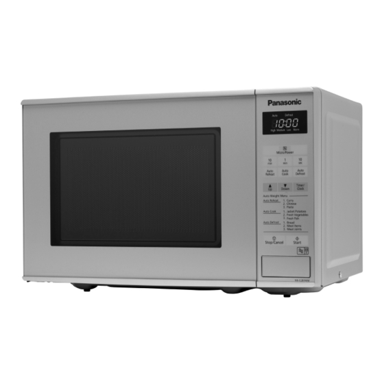
Microwave Oven
Model No.
NN-E271WM
NN-E281BM
/
Black
1

Advertisement

Table of Contents
loading

Summary of Contents for Panasonic NN-E271WM

  • Page 1 (H) x 340(D) mm Cavity Dimensions 306(W) x 215(H) x 308 (D) mm Net Weight 11kg (approx.) Shipping weight 13 kg (approx.) Specifications subject to change without notice. © Panasonic Corporation 201 Unauthorized copying and distribution is a violation of law...
  • Page 2: Safety Precautions

      WARNING     This product should be serviced only by trained qualified personnel.  This service manual covers products for following markets.  When troubleshooting or replacing parts, please refer to the country identifications shown below for your  applicable product specification.    B PQ……For UK    GPG……For Germany    WPG……Switzerland    ZPE……For CIS countries  SAFETY PRECAUTIONS This device is to be serviced only by properly qualified service personnel. Consult the service manual for proper service procedures to assure continued safety operation and for precautions to be taken to avoid possible exposure to excessive microwave energy.
  • Page 3: Table Of Contents

    CONTENTS (Page) SAFETY PRECAUTIONS - - - - - - - - - - - - - - - - - - - - - - - - - - - - - - - - - - - - - - - - - - - - - - - - - - - - - - - - - - - - - - - - - - - - - Inside front cover SPECIFICATIONS - - - - - - - - - - - - - - - - - - - - - - - - - - - - - - - - - - - - - - - - - - - - - - - - - - - - - - - - - - - - - - - - - - - - - - - - - - - - - - - - - - - - - - - - - - - - - - - - - - - - - 1-1 CAUTIONS - - - - - - - - - - - - - - - - - - - - - - - - - - - - - - - - - - - - - - - - - - - - - - - - - - - - - - - - - - - - - - - - - - - - - - - - - - - - - - - - - - - - - - - - - - - - - - - - - - - - - - - - - - - - - - 2-1 INSTALLATIONS - - - - - - - - - - - - - - - - - - - - - - - - - - - - - - - - - - - - - - - - - - - - - - - - - - - - - - - - - - - - - - - - - - - - - - - - - - - - - - - - - - - - - - - - - - - - - - - - - - - - - - 3-1...
  • Page 4 POWER LEVEL & ACCESSORIES ITEM DESCRIPTION Control Complement Microwave Power for Variable Cooking Power level 800 Watts High 270 Watts Defrost Medium 700 Watts 520 Watts Warm 200 Watts Rating Label Location Inside Accessories Instruction manual Glass Tray ller ing This microwave oven is designed for household use only.
  • Page 5: Cautions

    CAUTIONS Unlike other appliances, the microwave oven is MICROWAVE RADIATION high-voltage and high-current equipment. Personnel should not be exposed to the Though it is free from danger in ordinary use, microwave energy which may radiate from the extreme care should be taken during repair. magnetron or other microwave generating device if it is improperly used or connection.
  • Page 6: Installations

    INSTALLATIONS BEFORE YOU BEGIN, READ THE FOLLOWING INSTRUCTIONS COMPLETELY AND CAREFULLY. INSTALLING EARTHING INSTRUCTIONS 1. Empty the microwave oven and clean inside it with This microwave oven is designed to be used in a fully a soft, damp cloth. Check for damage such as earthed condition.
  • Page 7: Operating Instructions

    OPERATING INSTRUCTIONS FEATURES Oven Front Plate See-Through oven window Door C Control Panel Safety Door Lock System Glass Tray Roller Ring CONTROL PANEL (1) Display Window (2) Microwave Power Levels (3) Time Pads (4) Auto Weight Reheat Programs (5) Auto Weight Cook Programs (6) Auto Weight Defrost Pad (7) Timer / Clock Pad (8) Weight Selection Pads...
  • Page 8: Operating Sequence

    OPERATING SEQUENCE The following is a description of component functions 5. AUTO WEIGHT DEFROST during oven operation. Desired Desired Stop/ defrost Start 1. SETTING THE CLOCK weight Cancel program Set the time 6. AUTO WEIGHT REHEAT Stop/ by pressing Clock Clock Cancel time pads...
  • Page 9: Circuit Description

    CIRCUIT DESCRIPTION power of microwave oven as POWER LEVEL. GENERAL DETAILS (refer to page 1-1) • The low voltage transformer supplies the necessary voltage to the micom controller when power cord is WHEN THE DOOR IS OPENED DURING plugged in. COOKING •...
  • Page 10: Service Information

    SERVICE INFORMATION TOOLS AND MEASURING INSTRUMENTS NECESSARY TOOLS NECESSARY MEASURING INSTRUMENTS Tools normally used for TV servicing are sufficient. • TESTER(VOLTS-DC, AC., Ohmmeter) Standard tools are listed below. • Microwave survey meter • Diagonal pliers - Holaday HI-1500 • Long nose pliers HI-1501 •...
  • Page 11 MEASUREMENT WITH OUTER CASE NOTES WHEN MEASURING REMOVED • Do not exceed meter full scale deflection. • The test probe must be removed no faster than • When you replace the magnetron, measure for 1 inch/sec (2.5 cm/sec) along the shaded area, microwave energy leakage before the outer case is otherwise a false reading may result.
  • Page 12: Measurement Of Microwave Power Output

    MEASUREMENT OF MICROWAVE POWER OUTPUT • Microwave power output measurement is made with is measured while the microwave generator is the microwave oven supplied at its rated voltage and operating at full power. Magnetron filament heat-up operated at its maximum microwave power setting with time is not included.
  • Page 13 D. DOOR ASSEMBLY REMOVAL E. HIGH VOLTAGE TRANSFORMER REMOVAL 1) Open the door. 2) Remove two screws holding the Hinge 1) Discharge the high voltage capacitor. to the Cavity Ass'y. 2) Disconnect the leadwire from magnetron, high voltage CAUTION : Be careful not to damage Door C transformer, and capacitor.
  • Page 14 H. AIR GUIDE ASSEMBLY REMOVAL J. REMOVING THE TURNTABLE MOTOR 1) Disconnect the leadwire from lamp, A.C Relay and 1) Remove the glass tray monitor resistor and magnetron. 2) Remove the pully shaft VERY CAREFULLY 3) Lay the unit down on its back. 2) Remove the screw to the cavity.
  • Page 15 K. PCB ASSEMBLY REMOVAL L. INTERLOCK SYSTEM 1) Remove the control panel assembly from the 1) INTERLOCK MECHANISM cavity. The door lock mechanism is a device which has been specially designed to eliminate completely 2) Remove screws which hold the PCB to microwave activity when the door is opened during control panel.
  • Page 16: Interlock Continuity Test

    INTERLOCK CONTINUITY TEST WARNING : FOR CONTINUED PROTECTION AGAINST EXCESSIVE RADIATION EMISSION, REPLACE ONLY WITH IDENTICAL REPLACEMENT PARTS. TYPE NO. KW3A FOR SWITCHS B. SECONDARY INTERLOCK SWITCH TEST A. PRIMARY INTERLOCK SWITCH TEST Disconnect the wire lead from the secondary When the door release button is depressed slowly switch.
  • Page 17: Component Test Procedure

    COMPONENT TEST PROCEDURE CAUTIONS 1. DISCONNECT THE POWER SUPPLY CORD FROM THE OUTLET WHENEVER REMOVING THE OUTER CASE FROM THE UNIT. PROCEED WITH THE TEST ONLY AFTER DISCHARGING THE HIGH VOLTAGE CAPACITOR AND REMOVING THE WIRE LEADS FROM THE PRIMARY WINDING OF THE HIGH VOLTAGE TRANSFORMER.
  • Page 18 COMPONENTS TEST PROCEDURE RESULTS Antenna Gasket Chassis Filament NOTE: When testing the magnetron, be sure to install the magnetron gasket in the correct position and be sure that the gasket is in good condition. HIGH VOLTAGE Measure the resistance. Normal: Momentarily indicates CAPACITOR (Ohm-meter scale: Rx1000) several ohms, and then...
  • Page 19 COMPONENTS TEST PROCEDURE RESULTS FUSE Check for continuity of the fuse with an Normal Abnormal multi-meter. NOTE: If the fuse is blown, check the primary, the secondary, and the monitor switches, H.V.D. and H.V.C. before replacing the fuse. If the fuse is blown by improper switch operation replace the defective switch and the fuse at the same time.
  • Page 20 COMPONENTS TEST PROCEDURE RESULTS Ω FAN MOTOR Measure the resistance. Normal: 00~500 Abnormal: ∞ or several Ω (Wire leads removed) (Ohm-meter scale: R x 100) Ω Measure the resistance. TURNTABLE Normal: Approx. 100~200K Abnormal: ∞ or several Ω (Ohm-meter scale: R x 1000) MOTOR (Wire leads removed) NOTE : •...
  • Page 21: Trouble Shooting

    TROUBLE SHOOTING WHEN YOU GET A COMPLAINT FROM YOUR CUSTOMER, EVALUATE THE COMPLAINT CAREFULLY. IF THE FOLLOWING SYMPTOMS APPLY, PLEASE INSTRUCT THE CUSTOMER IN THE PROPER USE OF THE MICROWAVE OVEN. THIS CAN ELIMINATE AN UNNECESSARY SERVICE CALL. CAUTIONS 1. Check grounding before checking for trouble. 2.
  • Page 22 (TROUBLE 1) The following visual conditions indicate a probable defective control circuit. 1. Incomplete segments. • Segment missing. • Partial segment missing. • Digit flickering (NOTE: Slight flickering is normal.) 2. Colon does not turn on or blink. 3. A distinct change in the brightness of one or more numbers in display. 4.
  • Page 23 (TROUBLE 2) Oven does not operate at all ; Display window does not display any figures and no input is accepted. CONDITION CHECK RESULT CAUSE REMEDY Replace primary Malfunction of the Check continuity 1. Fuse blows. Continuity. and monitor monitor switch. of monitor switches.
  • Page 24 (TROUBLE 3) Display shows all figures set, but oven does not start cooking while desired program times are set and START pad is touched. CONDITION CHECK RESULT CAUSE REMEDY Defective Replace Check continuity 1.Setting time does No continuity. secondary switch. secondary switch.
  • Page 25 (TROUBLE 5) No microwave oscillation even though oven lamp and fan motor run (Display operates properly) CONDITION CHECK RESULT CAUSE REMEDY Defective P.C.B No microwave Disconnect the Replace P.C.B No continuity. oscillation. wire leads from assembly assembly relay 2 and check continuity Continuity.
  • Page 26 (TROUBLE 6) Oven does not cook properly when programmed for the set power level (Operates properly on HIGH) CONDITION CHECK RESULT CAUSE REMEDY Output is full when Defective P.C.B. Replace P.C.B. Disconnect the Abnormal. you set lower assembly. assembly. wire leads from power level.
  • Page 27 Jun, 20 P/NO : Printed in China...

This manual is also suitable for:

Nn-e281bm

Table of Contents