Table of Contents
Advertisement
Quick Links
Advertisement
Table of Contents

Subscribe to Our Youtube Channel
Related Manuals for ACTi E44A


Summary of Contents for ACTi E44A
- Page 1 Bullet Camera Hardware Manual E44A, E45A, E46A Ver. 2014/10/20...
-
Page 2: Table Of Contents
How to Connect DI/DO Devices (Optional) ........23 How to Connect Audio Input / Output Devices (Optional) ... 26 Other Adjustments and Accessories Adjust the Viewing Angle ............... 27 Attach the Sunshield ..............28 Reset the Camera ................29 How to Reset the Camera? ............29 www.acti.com... - Page 3 Hardware Manual Accessing the Camera Configure the IP Addresses ............33 Using DHCP Server to Assign IP Addresses ........ 33 Using the Default Camera IP Address .......... 40 Access the Camera ................. 42 www.acti.com...
-
Page 4: Precautions
Every reasonable care has been taken during the writing of this manual. Please inform your local office if you find any inaccuracies or omissions. We cannot be held responsible for any typographical or technical errors and reserve the right to make changes to the product and manuals without prior notice. www.acti.com... - Page 5 This product has been tested and found to comply with the limits for Class B Information Technology Equipment according to European Standard EN 55022 and EN 55024. In a domestic environment, this product may cause radio interference in which cause the user may be required to take adequate measures. www.acti.com...
-
Page 6: Safety Instructions
Safety Check Upon completion of any service or repairs to this video product, ask the service technician to perform safety checks to determine if the video product is in proper operating condition. www.acti.com... -
Page 7: Introduction
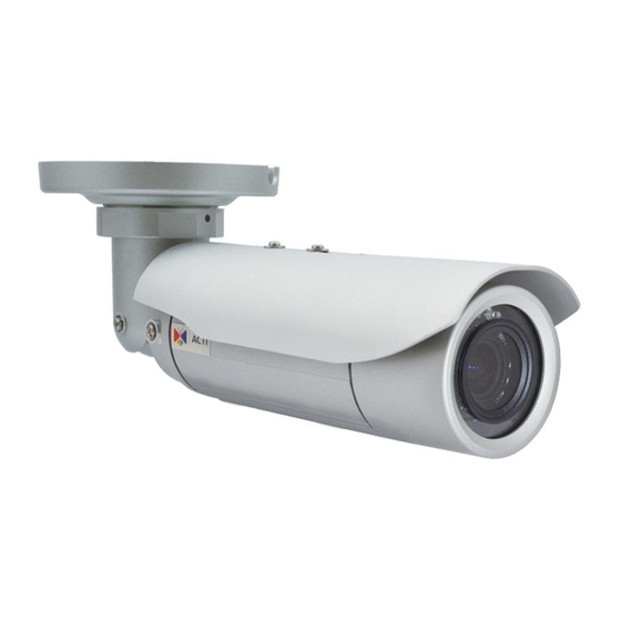
Hardware Manual Introduction List of Models This hardware manual contains the following models: 2MP Bullet with D/N, Adaptive IR, Basic WDR, SLLS, Vari-focal E44A lens 1MP Bullet with D/N, Adaptive IR, Superior WDR, Vari-focal E45A lens 3MP Bullet with D/N, Adaptive IR, Superior WDR, Vari-focal... -
Page 8: Package Contents
Hardware Manual Package Contents Camera Bracket Plate Sunshield Drill Template Mounting Screw Kit Sunshield Screw Kit Conduit Gland Cable Gland Washer Warranty Card Quick Installation Guide www.acti.com... -
Page 9: Physical Description
Digital Input (DI) and Digital Output (DO) devices are used in applications like motion detection, event triggering, alarm notifications, etc. See How to Connect DI/DO Devices (Optional) on page 23 for information on how to connect DI/DO devices to your camera. www.acti.com... -
Page 10: Installation Procedures
2. Detach the integrated body from the camera back cover. 3. Remove the clamping nut and rubber insert to loosen the cable within the gland. NOTE: Connectors are connected inside the camera, be careful when pulling the rubber insert from the gland. www.acti.com... - Page 11 5. Insert the memory card, with the metallic contacts facing down, into the slot until it clicks into place. 6. Before closing the back cover, make sure the Ethernet cable connector is connected to the main board. If the cable is disconnected, connect as shown below. www.acti.com...
- Page 12 8. Push the rubber insert into the gland and attach the clamping nut. NOTE: Make sure the clamping nut is tightly attached to ensure that the connection is waterproof. 9. Attach the integrated bracket and secure the three (3) screws. www.acti.com...
-
Page 13: Step 2: Mount The Camera
(3) holes and use the supplied screw tox. 3. Attach the camera to the surface using the three (3) supplied screws. 4. Adjust the camera installation angle and orientation, and then tighten the two (2) screws to fix its position. www.acti.com... -
Page 14: Step 3: Waterproof And Connect The Cable(S)
How to Use the Conduit Gland on page 18. NOTE: The flex conduit is not included in the package and must be purchased separately. Audio and digital input/output devices can be connected to the camera, for more information, Other Connections on page 23. www.acti.com... -
Page 15: How To Use The Cable Gland
Exterior-grade cables are already waterproof. Not included in the package. Washer (included in the camera package) Perform the following to waterproof the “pigtail” using the cable gland: 1. Disassemble the cable gland as shown below: Clamping Sealing Cable Gland Insert www.acti.com... - Page 16 Hardware Manual 2. Insert the clamping nut into the Ethernet cable. 3. Insert the sealing insert with claw. 4. Insert the gland body into the Ethernet cable. 5. On the “pigtail” side, insert the washer into the “pigtail”. www.acti.com...
- Page 17 8. Insert the sealing insert into the cable gland body and then attach the clamping nut to complete the cable solution. NOTE: Make sure the clamping nut is tightly attached to the cable gland body and the sealing insert is squeezed tightly. www.acti.com...
-
Page 18: How To Use The Conduit Gland
Washer CAT 5 or CAT 6 (included in the camera package) (not included in the package) Perform the following to waterproof the “pigtail” using the conduit gland: 1. Disassemble the conduit gland as shown below: Sealing Clamping Cable Gland www.acti.com... - Page 19 2. Pull the Ethernet cable through the flex conduit. Leave enough length of the cable outside the flex conduit. 3. Insert the clamping nut through the flex conduit. 4. Insert the sealing nut and fix it at the end of the flex conduit. 5. Insert the gland body into the Ethernet cable. www.acti.com...
- Page 20 6. On the “pigtail” side, insert the washer into the “pigtail”. 7. Connect the Ethernet cable connector to the “pigtail” connector. 8. Attach the gland body to the “pigtail”. Make sure the gland body is tightly attached to the “pigtail” and the washer is NOTE: secured between them. www.acti.com...
- Page 21 9. Push the flex conduit and insert the sealing nut into the gland body. NOTE: Make sure the clamping nut is tightly attached to the cable gland body and the sealing insert is squeezed tightly. 10. Attach the clamping nut to complete the cable solution. www.acti.com...
-
Page 22: Step 4: Connect To Network
Power Cable PoE Injector Ethernet Cable AC Power (Data + Power) Source Camera Step 5: Access the Camera Live View Accessing the Camera on page 33 for more information on how to access the Live View of the camera. www.acti.com... -
Page 23: Other Connections
For example, you can connect an “alarm horn” to the camera; as such when an event occurs inside the camera (e.g. detected intruder), the alarm horn will sound. Other common DO device applications are motion-triggered lights, electric fence, magnetic door locks, etc. www.acti.com... - Page 24 TTL - compatible logic levels To trigger (low) Logic level 0: 0V ~ 0.4V Voltage Normal (high) Logic level 1: 3.1V ~ 30V Current 10mA ~ 100mA Connection design Transistor (Open Collector) Voltage & Current < 24V DC, < 50mA www.acti.com...
- Page 25 Note that when choosing an appropriate relay, please refer to its specifications and make sure they match the above design. The triggering circuit voltage has to be around 12V DC and the switch-controlled circuit voltage has to match the external power supply (e.g. 110V AC or 220V AC). www.acti.com...
-
Page 26: How To Connect Audio Input / Output Devices (Optional)
For more information on DI/DO connections, please refer to the Knowledge Base article All about Digital Input and Digital Output downloadable from the link below (http://www.acti.com/kb/detail.asp?KB_ID=KB20091230001). How to Connect Audio Input / Output Devices (Optional) If using an audio input device, such as a microphone with a built-in amplifier, connect the device to the Audio Input jack (RED) of the camera. -
Page 27: Other Adjustments And Accessories
2. Based on the live view from the camera, adjust the focal length and focus of the target area. Focal Length Focus 3. When done, close the front cover. CAUTION: The front cover must be tightly closed to ensure water or dust does not go through any opening. www.acti.com... -
Page 28: Attach The Sunshield
1. Loosely secure the supplied screws and washers to attach the sunshield. 2. Slide to adjust the sunshield to cover the lens as far as possible but out of the camera’s live view. 3. Tighten the screws to fix the position of the sunshield. See final installation below. www.acti.com... -
Page 29: Reset The Camera
How to Reset the Camera? Do the following procedures to access the Reset button and restore the camera its default factory settings. 1. Remove the three (3) screws securing the integrated bracket. 2. Detach the integrated body from the camera back cover. www.acti.com... - Page 30 Connectors are connected inside the camera, be careful when pulling the rubber insert from the gland. 4. Twist to open the back cover and slowly lift the cover. 5. To reset the camera, press and hold the Reset button for at least 5 seconds or until the LED lights up. www.acti.com...
- Page 31 If the cable is disconnected, connect as shown below. 7. Attach the back cover. 8. Push the rubber insert into the gland and attach the clamping nut. NOTE: Make sure the clamping nut is tightly attached to ensure that the connection is waterproof. www.acti.com...
- Page 32 Hardware Manual 9. Attach the integrated bracket and secure the three (3) screws. www.acti.com...
-
Page 33: Accessing The Camera
Windows system – just by pressing the “Network” icon, all the cameras of the local area network will be discovered by Windows thanks to the UPnP function support of our cameras. In the example below, we successfully found the camera model that we had just connected to the network. www.acti.com... - Page 34 The IP Utility can be downloaded for free from http://www.acti.com/IP_Utility With just one click, you can launch the IP Utility and there will be an instant report as follows: You can quickly see the camera model in the list. Click on the IP address to automatically launch the default browser of the PC with the IP address of the target camera filled in the address bar of the browser already.
-
Page 35: Using The Default Camera Ip Address
PC has to be configured to match the network segment of the camera. Manually adjust the IP address of the PC: In the following example, based on Windows 7, we will configure the IP address to 192.168.0.99 and set Subnet Mask to 255.255.255.0 by using the steps below: www.acti.com... - Page 36 In such case, please plug in only one camera at a time, and change its IP address by using the Web browser before plugging in the next one. This way, the Web browser will not be confused about two devices having the same IP address at the same time. www.acti.com...
-
Page 37: Access The Camera
When using Internet Explorer browser, the ActiveX control for video stream management will be downloaded from the camera directly – the user just has to accept the use of such control when prompted so. No other third party utilities are required to be installed in such case. www.acti.com... - Page 38 HTTP port of the camera is 80, which can be omitted from the address for convenience. Before logging in, you need to know the factory default Account and Password of the camera. Account: Admin Password: 123456 www.acti.com...
- Page 39 Copyright © 2014, ACTi Corporation All Rights Reserved 7F, No. 1, Alley 20, Lane 407, Sec. 2, Ti-Ding Blvd., Neihu District, Taipei, Taiwan 114, R.O.C. TEL : +886-2-2656-2588 FAX : +886-2-2656-2599 Email: sales@acti.com...
Need help?
Do you have a question about the E44A and is the answer not in the manual?
Questions and answers