Table of Contents
Advertisement
Quick Links
One Technology Way • P.O. Box 9106 • Norwood, MA 02062-9106, U.S.A. • Tel: 781.329.4700 • Fax: 781.461.3113 •
Evaluation Board for Single High Speed Selectable Gain Differential Amplifiers
FEATURES
Enables quick breadboarding/prototyping
Selectable gain of 1, 2, or 3
Edge-mounted SMA connector provisions
Easy connection to test equipment and other circuits
GENERAL DESCRIPTION
The 16-lead, 3 mm × 3 mm lead frame chip scale package
(LFCSP) evaluation board is designed to aid in the evaluation of
single, high speed, selectable gain differential amplifiers. It has the
flexibility to choose between a gain of 1, 2, or 3. The evaluation
board is a bare board (that is, there are no components soldered
to the board) that enables users to quickly prototype a variety of
differential amplifier circuits, which minimizes risk and reduces
time to market. The evaluation board supports any of Analog
Devices, Inc., single, high speed differential amplifiers in 3 mm
× 3 mm LFCSP packages.
NOTES
1. THE EVALUATION BOARD SILKSCREEN PART NUMBER
LABELING ON YOUR BOARD MAY BE DIFFERENT FROM
WHAT IS SHOWN HERE.
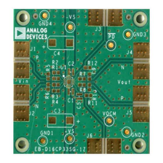
Figure 1. Component Side of the Evaluation Board
PLEASE SEE THE LAST PAGE FOR AN IMPORTANT
WARNING AND LEGAL TERMS AND CONDITIONS.
(16-Lead, 3 mm × 3 mm LFCSP)
DIGITAL PICTURES OF THE EVALUATION BOARD
Rev. A | Page 1 of 8
Evaluation Board User Guide
Figure 1 and Figure 2 show the component side and circuit side
of the evaluation board. Figure 3 shows the evaluation board
schematic.
The 4-layer evaluation board accepts edge-mounted Subminiature
Version A (SMA) connectors on both inputs and outputs, which
allows efficient and quick connection to test equipment or other
circuitry.
The board ground plane, component placement, and power supply
bypassing have been optimized for maximum circuit flexibility
and performance. The evaluation board uses a variety of surface-
mount technology (SMT) component case sizes: 0508, 0603,
and 7343.
Figure 4 and Figure 6 show the evaluation board assembly drawings.
The metal layout pattern for connecting the board to the op amp
and to the supporting circuitry is shown in Figure 5 and Figure 7.
NOTES
1. THE EVALUATION BOARD SILKSCREEN PART NUMBER
LABELING ON YOUR BOARD MAY BE DIFFERENT FROM
WHAT IS SHOWN HERE.
Figure 2. Circuit Side of the Evaluation Board
UG-102
www.analog.com
Advertisement
Table of Contents

Related Manuals for Analog Devices UG-102


Summary of Contents for Analog Devices UG-102
- Page 1 Evaluation Board User Guide UG-102 One Technology Way • P.O. Box 9106 • Norwood, MA 02062-9106, U.S.A. • Tel: 781.329.4700 • Fax: 781.461.3113 • www.analog.com Evaluation Board for Single High Speed Selectable Gain Differential Amplifiers (16-Lead, 3 mm × 3 mm LFCSP)
- Page 2 UG-102 Evaluation Board User Guide TABLE OF CONTENTS Features ....................1 Evaluation Board Schematic ............3 General Description ................. 1 Assembly Drawings and Board Layouts .........4 Digital Pictures of the Evaluation Board ........1 Ordering Information ...............5 Revision History ................2 Bill of Materials ................5...
- Page 3 Evaluation Board User Guide UG-102 EVALUATION BOARD SCHEMATIC Figure 3. Single Differential Amplifier Evaluation Board Schematic Rev. A | Page 3 of 8...
- Page 4 UG-102 Evaluation Board User Guide ASSEMBLY DRAWINGS AND BOARD LAYOUTS Figure 4. Board Assembly Drawing, Component Side Figure 6. Board Assembly Drawing, Circuit Side Figure 5. Board Layout Pattern, Component Side Figure 7. Board Layout Pattern, Circuit Side Rev. A | Page 4 of 8...
- Page 5 Evaluation Board User Guide UG-102 ORDERING INFORMATION BILL OF MATERIALS Table 1. Quantity Reference Designator Description Package +VS, PD, −VS, VOCM CONN-PCB test point blue CNLOOPTP C1, C2, C5 0.1 µF capacitors 0508 C3, C4 10 µF capacitors 7343 GND1 to GND4...
- Page 6 UG-102 Evaluation Board User Guide NOTES Rev. A | Page 6 of 8...
- Page 7 Evaluation Board User Guide UG-102 NOTES Rev. A | Page 7 of 8...
- Page 8 By using the evaluation board discussed herein (together with any tools, components documentation or support materials, the “Evaluation Board”), you are agreeing to be bound by the terms and conditions set forth below (“Agreement”) unless you have purchased the Evaluation Board, in which case the Analog Devices Standard Terms and Conditions of Sale shall govern. Do not use the Evaluation Board until you have read and agreed to the Agreement.
Need help?
Do you have a question about the UG-102 and is the answer not in the manual?
Questions and answers