Table of Contents
Advertisement
Quick Links
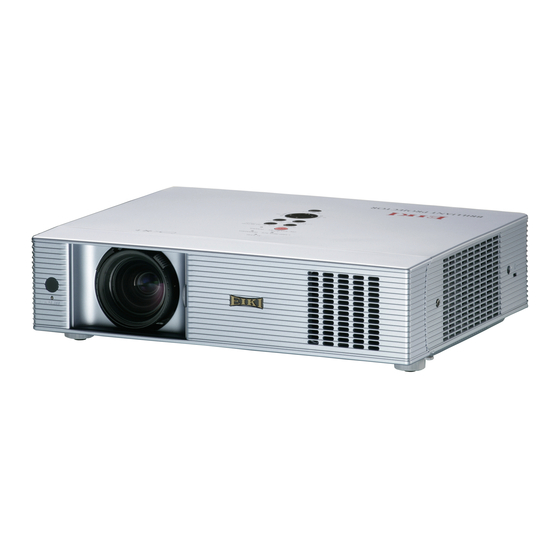
Multimedia Projector
MODEL
LC-WB42NA
Owner's Manual
Network Supported
□ Wireless LAN
IEEE802.11b/g/n
□ Wired LAN
100-Base-TX/10-Base-T
Memory Viewer
USB Memory Viewer
□
* Refer to the owner's manuals below for details
about network and memory viewer function.
Network Set-up and Operation
■
Memory viewer function
■
Advertisement
Table of Contents

Related Manuals for Eiki LC-WB42NA


Summary of Contents for Eiki LC-WB42NA
- Page 1 Multimedia Projector Network Supported □ Wireless LAN IEEE802.11b/g/n □ Wired LAN 100-Base-TX/10-Base-T MODEL LC-WB42NA Memory Viewer USB Memory Viewer □ * Refer to the owner’s manuals below for details about network and memory viewer function. Network Set-up and Operation ■ Memory viewer function ■...
-
Page 2: Features And Design
Features and Design This Multimedia Projector is designed with the most advanced technology for portability, durability, and ease of use. This projector utilizes built-in multimedia features, a palette of 16.77 million colors, and matrix liquid crystal display (LCD) technology. ♦ - You can project an image on a computer as well as Compact Design operate and manage the projector via network. -
Page 3: Table Of Contents
Table of Contents Input Source Selection (Computer 2: RGB) Features and Design . . . . . . . . . . . . . . . . . . .2 Computer System Selection Table of Contents . -
Page 4: To The Owner
To the Owner Before installing and operating this projector, read this Safety Precaution manual thoroughly. This projector provides many convenient features and WARNING: ● THIS APPARATUS MUST BE EARTHED. functions. Operating the projector properly enables ● TO REDUCE THE RISK OF FIRE OR you to manage those features and maintains it in good ELECTRIC SHOCK, DO NOT EXPOSE THIS condition for many years to come. -
Page 5: Safety Instructions
Safety Instructions All the safety and operating instructions should be read Do not install the projector near the ventilation duct of before the product is operated. air-conditioning equipment. Read all of the instructions given here and retain them This projector should be operated only from the type for later use. -
Page 6: Air Circulation
Safety Instructions Air Circulation Moving the Projector Openings in the cabinet are provided for ventilation. To When moving the projector, close the Slide Shutter and ensure reliable operation of the product and to protect it retract adjustable feet to prevent damage to the lens from overheating, these openings must not be blocked and cabinet. -
Page 7: Installing The Projector In Proper Directions
Safety Instructions Installing the Projector in Proper Directions Use the projector properly in specified positions. Improper positioning may reduce the lamp life and result in severe accident or fire hazard. This projector can project the picture upward, downward or backward, perpendicular to the plane of the screen as shown in the figure below. -
Page 8: Compliance
Do not make any changes or modifications to the equipment unless otherwise specified in the instructions. If such changes or modifications should be made, you could be required to stop operation of the equipment. Model Number : LC-WB42NA Trade Name : EIKI Responsible party : EIKI International,Inc. -
Page 9: Part Names And Functions
Part Names and Functions Front ① Infrared Remote Receiver ② WIRELESS Indicator ③ Focus Ring ④ Projection Lens ⑤ Zoom Lever ⑥ Slide Shutter CAUTION Do not turn on a projector with slide shutter closed. High temperature from light beam may damage slide shutter and result in fire hazard. ⑦... -
Page 10: Rear Terminal
Part Names and Functions Rear Terminal ⑤ ⑥ ① ② ③ ④ ⑦ ⑬ ⑫ ⑪ ⑩ ⑨ ⑧ ① R/C jACK ⑧ USB Connector (Series A) Connect the USB menory (refer to the owner’s When using the wired remote control, connect manual “Network Set-up and Operation”). the wired remote control to this jack with a remote control cable (supplied). -
Page 11: Top Control
Part Names and Functions Top Control ⑩ ⑥ ⑨ ⑤ ④ ⑧ ⑦ ③ ② ① ① SELECT button ⑥ WARNING indicator – Execute the selected item (p.24). – Lights red when the projector detects an abnormal – Expand or compress the image in the Digital zoom condition. -
Page 12: Remote Control
Part Names and Functions Remote Control ⑤ LASER LIGHT window A laser beam is emitted from here (p.14). ⑥ HDMI button Select the HDMI input source. (pp.28,41) ① ⑦ COMPUTER button Select the COMPUTER input source. (pp.30-31, 41) ③ ⑤ ② ④ ⑧ INFO . button Operate the information function. (p.63) ⑨... -
Page 13: Remote Control Battery Installation
Part Names and Functions Remote Control Battery Installation Open the battery Install new batteries Replace the compartment lid. into the compartment. compartment lid. Press the lid Two AAA size batteries downward and slide it. For correct polarity (+ and –), be sure battery terminals are in contact with pins in compartment. -
Page 14: Laser Pointer Function
Part Names and Functions Laser Pointer Function This remote control emits a laser beam from the laser light window. Press the LASER button to activate the laser pointer. The signal emission indicator lights red and the red laser beam is emitted. If the LASER button is pressed for more than one minute or if it is released, the laser light goes off. -
Page 15: Wireless Mouse Operation
Part Names and Functions Wireless Mouse Operation The remote control can be used as a wireless mouse for your computer. Before operating the wireless mouse, connect your computer and the projector with a USB cable (not supplied). See “Connecting to a PRESENTATION POINTER Computer” on page 17. When the Pointer button function is used, the wireless mouse is not Move the pointer on the screen... -
Page 16: Installation
Installation Positioning the Projector For projector positioning, see the figures below. The projector should be set perpendicularly to the plane of the screen. Note: • The brightness in the room has a great influence on picture quality. It is recommended to limit ambient lighting in order to obtain the best image. -
Page 17: Connecting To A Computer
Installation Connecting to a Computer Cables used for connection • VGA cables (Mini D-sub 15 pin) * • USB cable • Audio cables • HDMI-DVI cable (*One cable is supplied; other cables are not supplied with the projector.) Monitor Monitor Output / Output Audio Output Output Monitor Input External Audio Equipment USB cable... -
Page 18: Connecting To Video Equipment
Installation Connecting to Video Equipment Cables used for connection • Video and Audio cable (RCA x 3) • S-video cable • Audio cable (Cables are not supplied with the projector. ) External Audio Equipment Video and Audio Output Audio Input (Video) S-video Output S-video cable Video and Audio cable Audio cable (stereo) AUDIO OUT (stereo) -
Page 19: Connecting To Component Video Equipment
Installation Connecting to Component Video Equipment Cables used for connection • Audio cables • Scart-VGA cable • Component cable • HDMI cable • Component-VGA cable (Cables are not supplied with this projector.) Audio RGB Scart 21- Component Video Output Output pin Output (Y, Pb/Cb, Pr/Cr) HDMI Output Component cable Scart-VGA... -
Page 20: Connecting The Ac Power Cord
Installation Connecting the AC Power Cord This projector uses nominal input voltages of 100-120 V or 200–240 V AC and it automatically selects the correct input voltage. It is designed to work with single-phase power systems having a grounded neutral conductor. To reduce the risk of electrical shock, do not plug into any other type of power system. -
Page 21: Basic Operation
Connect the projector’s AC power cord into an AC outlet. The POWER indicator lights red. Open the slide shutter (see pages 9, 66). http://www.eiki.com Press the ON/SYAND-BY button on the top control or on the remote control. The POWER indicator lights The preparation display will disappear green and the cooling fans start to operate. - Page 22 Basic Operation Enter a PIN code Use the Point buttons to enter a number. Press the ▲▼ PIN Code Input Dialog Box Point button to fix the number and move the red frame ► pointer to the next box. The number changes to . If you fixed an incorrect number, use the Point button to move ◄...
-
Page 23: Turning Off The Projector
Basic Operation Turning Off the Projector Press the ON/STAND-BY button on the top control or on the remote control, and Power off? appears on the screen. Press the ON/STAND-BY button again to turn off the projector. The POWER indicator starts to blink red, and the cooling fans keep running (You can select the level of fans’... -
Page 24: How To Operate The On-Screen Menu
Basic Operation How to Operate the On-Screen Menu The projector can be adjusted or set via the On-Screen Top Control Menu. The menus have a hierarchical structure, with a main menu that is divided into submenus, which are further divided into other submenus. For each adjustment MENU button and setting procedure, refer to respective sections in this manual. -
Page 25: Menu Bar
Basic Operation Menu Bar For detailed functions of each menu, see “Menu Tree” on pages 73-74. Main Menu Sub-Menu Input Used to select an input source from Computer 1, Computer 2, HDMI, Video, S-video or Network (pp.30-31,40-41). -
Page 26: Zoom And Focus Adjustment
Basic Operation Zoom and Focus Adjustment Rotate the Zoom Lever to zoom in and out. Rotate the Focus Ring to adjust the focus of the image. Zoom Lever Auto Setup Function Focus Ring Auto setup function is provided to automatically execute the setting of Auto setup (includes Input search, Auto PC adj. -
Page 27: Sound Adjustment
Basic Operation Sound Adjustment Top Control Direct Operation VOLUME+/- buttons Volume Press the VOLUME+/– buttons on the top control or on the remote control to adjust the volume. The volume dialog box appears on the screen for a few seconds. Remote Control Mute VOLUME- button Press the MUTE button on the remote control to select On to temporarily turn off the sound. -
Page 28: Remote Control Operation
Basic Operation Remote Control Operation Using the remote control for some frequently used operations is advisable. Just pressing one of the buttons enables you to make the desired operation quickly without calling up the On-Screen Menu. HDMI/COMPUTER/VIDEO/NETWORK button Remote Control Press the HDMI, COMPUTER, VIDEO or NETWORK button on the remote control to select the input source. - Page 29 Basic Operation NO SHOW button Press the NO SHOW button on the remote control to black out the image. To restore to normal, press the NO SHOW button again or press any other button. When a projected image is captured and set as User in the Logo selection (see page 50), the screen changes each time you press the NO SHOW button as follows.
-
Page 30: Computer Input
Computer Input Input Source Selection (Computer 1: RGB / Component / RGB(Scart) ) Direct Operation Choose Computer 1 by pressing the INPUT button on the top control or press the COMPUTER button on the remote control. Before using these buttons, correct input source should be selected through Menu operation as described below. INPUT button Top Control Remote Control Computer 1 COMPUTER button... -
Page 31: Input Source Selection (Computer 2: Rgb)
Computer Input Input Source Selection (Computer 2: RGB) Direct Operation Choose Computer 2 by pressing the INPUT button on the top control or press the COMPUTER button on the remote control. INPUT button Top Control Remote Control Computer 1 COMPUTER button Computer 2 Computer 1 HDMI Computer 2 Video S-video Network COMPUTER 2 can not be selected when using the COMPUTER IN 2/ ... -
Page 32: Computer System Selection
Computer Input Computer System Selection This projector automatically tunes to various types of computers with its Multi-scan system and Auto PC adjustment. If a computer is selected as a signal source, this projector automatically detects the signal format and tunes to project a proper image without any additional settings. (Signal formats provided in this projector are shown on pages 76-77) One of the following messages may appear when: The projector cannot recognize the connected... -
Page 33: Auto Pc Adjustment
Computer Input Auto PC adjustment Auto PC adjustment function is provided to automatically adjust Fine sync, Total dots, Horizontal, Vertical, Clamp, Display area H and Display area V positions to conform to your computer. Menu Operation PC adjust Menu Auto PC adj . Press the MENU button to display the On-Screen Menu. Use the Point buttons to select PC adjust ▲▼... -
Page 34: Manual Pc Adjustment
Computer Input Manual PC adjustment Some computers employ special signal formats which may not be tuned by Multi-scan system of this projector. Manual PC adjustment enables you to precisely adjust several parameters to match those signal formats. The projector has five independent memory areas to store those parameters manually adjusted. It allows you to recall the setting for a specific computer. - Page 35 Computer Input Reset To reset the adjusted data, select Reset and press the SELECT button. A confirmation box appears and then select yes. All adjustments will return to their previous figures. Mode free Mode free To clear the stored data, select Mode free and then press the Point or the SELECT button.
-
Page 36: Image Mode Selection
Computer Input Image Mode Selection Direct Operation Remote Control IMAGE button Select the desired image mode among Dynamic, Standard, Real, Blackboard (Green), Colorboard, Image 1, Image 2, Dynamic Image 3 and Image 4 by pressing the IMAGE button on the remote control. Standard Real IMAGE button Blackboard (Green) Colorboard Image 1 Menu Operation Image 2 Press the MENU button to display the On-Screen Menu. Use the Point buttons to select Image select and ▲▼... -
Page 37: Image Adjustment
Computer Input Image Adjustment Press the MENU button to display the On-Screen Image Adjust Menu Menu. Use the Point buttons to select Image ▲▼ adjust and then press the Point ► the SELECT button. Use the Point buttons select the desired item ▲▼ and then press the SELECT button to display the adjustment dialog box. -
Page 38: Screen Size Adjustment
Computer Input Store To store the adjusted data, select Store and press the Point button. Use the Point buttons to select ► the SELECT ▲▼ one from Image 1 to 4 and press the SELECT button. A confirmation box appears and then select yes. Stored data can be called up by selecting an Image (1–4) in the Image Mode Selection on page 36. - Page 39 Computer Input Custom Adjust the screen scale and position manually with this function. Press the Point ►button at Custom and the Custom is displayed on the screen, you can use the Point ▲▼ buttons to choose the item you want to adjust. Scale H/V ..
-
Page 40: Video Input
Video Input Input Source Selection (Video, S-video) INPUT button Direct Operation Top Control Choose Video or S-video by pressing the INPUT button on Computer 1 the top control or the VIDEO button on the remote control. Computer 2 HDMI Remote Control Video VIDEO button Video S-video S-video Network COMPUTER 2 can not be selected when using the ... -
Page 41: Input Source Selection (Component, Rgb Scart 21-Pin, Hdmi)
Video Input Input Source Selection (Component, RGB Scart 21-pin, HDMI) Direct Operation Choose Computer 1 by pressing the INPUT button on the top control or press the COMPUTER button on the remote control; choose HDMI by pressing the INPUT button on the top control or press the HDMI button on the remote control. -
Page 42: Video System Selection
Video Input Video System Selection Press the MENU button to display the On-Screen AV System Menu (Video or S-video) Menu. Use the Point buttons to select Input and ▲▼ then press the Point or the SELECT button. ► HDMI Use the Point buttons to select Video , S-video ▲▼... -
Page 43: Image Mode Selection
Video Input Image Mode Selection Direct Operation IMAGE button Remote Control Select the desired image mode among Dynamic, Standard, Dynamic Cinema, Blackboard (Green), Colorboard, Image 1, Image 2, Image 3 and Image 4 by pressing the IMAGE Standard button on the remote control. Cinema Blackboard (Green) IMAGE button Colorboard Menu Operation Image 1 Press the MENU button to display the On-Screen Menu. Use the Point buttons to select Image select and ▲▼... -
Page 44: Image Adjustment
Video Input Image Adjustment Press the MENU button to display the On-Screen Image adjust Menu Menu. Use the Point buttons to select Image ▲▼ adjust and then press the Point or the SELECT ► button. Use the Point buttons select the desired item ▲▼ and then press the SELECT button to display the adjustment dialog box. - Page 45 Video Input Sharpness Press the Point button to decrease the sharpness of the ◄ image; press the Point button to increase the sharpness ► of the image (from 0 to 15). Gamma Use the Point buttons to adjust the gamma value to ◄►...
-
Page 46: Screen Size Adjustment
Video Input Screen Size Adjustment This projector has the picture screen resize function, which enables you to customize the image size. Press the MENU button to display the On-Screen Screen Menu Menu. Use the Point buttons to select Screen and ▲▼ then press the Point or SELECT button ►... -
Page 47: Setting
Setting Setting This projector has a Setting menu that allows you to set up Setting Menu the other various functions described below. Press the MENU button to display the On-Screen Menu. Press the Point buttons to select Setting ▲▼ and press the Point or the SELECT button to access ►... - Page 48 Setting Auto setup Auto setup This function enables Input search, Auto Keystone correction and Auto PC adjustment by pressing the AUTO SETUP/ CANCEL button on the top control or the AUTO SET/CANCEL button on the remote control. Settings for those functions can be altered as follows: Input search This function detects the input signal automatically.
- Page 49 Setting Keystone This function is used to store or reset the keystone Keystone correction when the AC power cord is unplugged. Store ..Keep the keystone correction even when the AC power cord is unplugged. Reset ..Release the keystone correction when the AC power cord is unplugged.
- Page 50 Setting Logo (Logo and Logo PIN code lock settings) Logo select This function allows you to customize the screen logo with Logo select, capture, Logo PIN code lock and Logo PIN code change functions. Note: When On is selected in the Logo PIN code lock function, HDMI setup Logo select, capture and Logo PIN code change Terminal Computer 2 cannot be selected.
- Page 51 Setting Capture This function enables you to capture an image being Capture projected to use it for a starting-up display or interval of presentations. Select Capture and press the SELECT button. A confirmation box appears and select yes to capture the projected image.
- Page 52 Setting Enter a Logo PIN code Enter a Logo PIN code Use the Point buttons to enter a number. Press the ▲▼ Point button to fix the number and move the red frame ► pointer to the next box. The number changes to . If you fixed an incorrect number, use the Point button to ◄...
- Page 53 Setting Ceiling Ceiling When this function is set to On, the picture will be top/ bottom and left/right reversed. This function is used to project the image from a ceiling-mounted projector. Rear Rear When this function is set to On, the picture will be left/right reversed.
- Page 54 Setting Pointer Pointer You can emphasize a part of the projected image with this function. Use the Point ▲▼ buttons to choose Spotlight (Large, Middle or Small) , Arrow, Finger or Dot and press the SELECT button. See "Pointer Function" on page 14. Arrow Standby mode This function is available when operating the projector via...
- Page 55 Setting Picture in Picture This function is used to project two videos simultaneously Picture in Picture by placing a separate small sub screen within the main screen. (Picture in Picture combinations provided in this projector are shown on pages 78.) Only the sound on the main picture is heard, the sound on the sub picture cannot be heard.( In P in P, the big picture is main picture, and the small one is sub picture;...
- Page 56 Setting Power management For reducing power consumption as well as maintaining Power management the lamp life, the Power management function turns off the projection lamp when the projector is not operated for a certain period. Select one of the following options: Timer left before Lamp is off. Ready ....
- Page 57 Setting On start When this function is set to On, the projector will be automatically turned on just by connecting the AC power cord to a wall outlet. Note: Be sure to turn off the projector properly (see "Turning Off the Projector" on page 23). If the projector is turned off in the incorrect sequence, the On start function does not work properly.
- Page 58 Setting Lamp control This function allows you to change brightness of the screen. Auto ... The brightness according to the input signal (between High and Eco mode). High ... Brighter than the Normal mode. Normal ..Normal brightness Eco .... Lower brightness reduces the lamp power consumption and extends the lamp life.
- Page 59 Setting Key lock Security (Key lock and PIN code lock) This function allows you to use the Key lock and PIN code lock function to set the security for the projector operation. Key lock This function locks the top control and remote control buttons to prevent operation by unauthorized persons..
- Page 60 Setting Enter a PIN code Use the Point buttons to enter a number. Press the Enter a PIN code ▲▼ Point button to fix the number and move the red frame ► pointer to the next box. The number changes to . If you fixed an incorrect number, use the Point button to ◄...
- Page 61 Setting This function provides the following options in the cooling fans’ operation when the projector is turned off (p.23). L1 ..Normal operation L2 ..Slower and lower-sound than the normal operation (L1), but it takes more time to cool the projector down.
- Page 62 Setting Filter counter This function is used to set a frequency for the filter Filter counter cleaning. When the projector reached a specified time between cleanings, a Filter warning icon appears on the screen, notifying the cleaning is necessary. After cleaning the filter, be sure to select Reset and set the timer.
-
Page 63: Information
Information Input Source Information Display The Information Menu is used for checking the status of the image signal being projected and the operation of the projector. Direct Operation Press the INFO. button on the remote control to display the Remote Control Information Menu. INFO . button Menu Operation Press the Point buttons to select Information. -
Page 64: Maintenance And Cleaning
Maintenance and Cleaning WARNING indicator The WARNING indicator shows the state of the function which protects the projector. Check the state of the WARNING indicator and the POWER indicator to take proper maintenance. The projector is shut down and the WARNING Top Control indicator is blinking red . When the temperature inside the projector reaches a WARNING blinking red certain level, the projector will be automatically shut down to protect the inside of the projector. -
Page 65: Cleaning The Filters
Maintenance and Cleaning Cleaning the Filters Filter prevents dust from accumulating on the optical elements inside the projector. Should the filters become clogged with dust particles, it will reduce cooling fans’ effectiveness and may result in internal heat buildup and adversely affect the life of the projector. If a Filter warning icon appears on the screen, clean the filters immediately. -
Page 66: Cleaning The Projection Lens
Maintenance and Cleaning Slide Shutter Slide Shutter is provided to protect the surface of the lens against scratches and dirt. When you are not using the projector, close the Slide Shutter. To open or close, slide the Slide Shutter on the front of the cabinet. -
Page 67: Lamp Replacement
See “Resetting the Lamp Counter” on the next page. Lamp ORDER REPLACEMENT LAMP Replacement lamp can be ordered through your dealer. When ordering a projection lamp, give the following information to the dealer. ● Model No . of your projector : LC-WB42NA ● Replacement Lamp Type No . : POA-LMP111 (Service Parts No . 610 333 9740) -
Page 68: Resetting The Lamp Counter
Maintenance and Cleaning Resetting the Lamp Counter Be sure to reset the Lamp counter after the lamp is replaced. When the Lamp counter is reset, the LAMP REPLACE indicator stops lighting and the Lamp replacement icon disappears. Press the MENU button to display the On-Screen Menu. -
Page 69: Troubleshooting
Appendix Troubleshooting Before calling your dealer or service center for assistance, check the items below once again. – Make sure you have properly connected the projector to peripheral equipment as described on pages 17-19. – Make sure all equipment is connected to AC outlet and the power is turned on. –... - Page 70 Appendix – Check the connection between your computer or video equipment No image and the projector. See pages 17-19. – See if the input signal is correctly output from your computer. Some laptop computers may need to change the setting for monitor output when connecting to a projector.
- Page 71 Appendix – Check PC adjustment or Screen and adjust them. The image is distorted or runs off . See pages 34-35, 38-39 . PIN code dialog box appears at – PIN code lock is being set. Enter a PIN code ("1234" or numbers start-up . you have set). See pages 22, 59-60. –...
- Page 72 Appendix WARNING : High voltages are used to operate this projector . Do not attempt to open the cabinet . If problems still persist after following all operating instructions, contact the dealer where you purchased the projector or the service center. Specify the model number and explain about the problem. We will advise you how to obtain service. This symbol on the nameplate The CE Mark is a Directive conformity means the product is Listed...
-
Page 73: Menu Tree
Appendix Menu Tree Computer Input/HDMI Input/Video Input Input Input Computer 1 Component RGB (Scart) Computer 2 HDMI Video S-video Network Sound Volume 0-63 Sound Mute On/Off Computer Input Dynamic Image Select Standard SVGA 1 System Real Mode 1 Blackboard (Green) Mode 2 Colorboard Red/Blue/Yellow/Green - - - - Image 1 Image 2 * Systems displayed in the System Menu vary... - Page 74 Appendix HDMI Input / Video Input Setting Auto Language 17 languages provided. Setting System 1080i Menu position 1035i Auto setup Input search Off/On1/On2 720p Auto PC adj. 575p On/Off 480p Auto Keystone 575i Auto 480i Manual Auto System Keystone Store/Reset Background Blue/User/Black SECAM Display On/Countdown off/Off NTSC Logo...
-
Page 75: Appendix
Appendix Indicators and Projector Condition Check the indicators for projector condition. Indicators Projector Condition LAMP WARNING POWER REPLACE red/green yellow The projector is off. (The AC power cord is unplugged.) The projector is in stand-by mode. Press the ON/STAND-BY button to turn on the projector. The projector is operating normally. -
Page 76: Compatible Computer Specifications
Appendix Compatible Computer Specifications Basically this projector can accept the signal from all computers with the V-, H-Frequency mentioned below and less than 140 MHz of Dot Clock for analog signal and 110 MHz of Dot Clock for digital signal. When selecting these modes, PC adjustment can be limited. - Page 77 Appendix When the input signal is digital from HDMI terminal, refer to the chart below. ON-SCREEN H-Freq. V-Freq. ON-SCREEN H-Freq. V-Freq. RESOLUTION RESOLUTION DISPLAY (KHz) (Hz) DISPLAY (KHz) (Hz) D-480p 640 x 480 31.47 59.88 D-SXGA1 1280 x 1024 63.98 60.02 D-480p 720 x 480...
-
Page 78: List Of Picture In Picture
Appendix List of Picture in Picture o : Picture in Picture combinations are enabled - : Picture in Picture combinations are disabled Note: • When the input signal(s) is/are incompatible, X mark will be displayed on the Main/Sub picture. • Depending on the frequency or signal type of PC/AV input, the display resolution may be lowered or images may not be displayed on the Main/Sub picture. -
Page 79: Technical Specifications
Appendix Technical Specifications Mechanical Information Projector Type Multi-media Projector Dimensions (W x H x D) 13.16" x 3.09" x 10.30 (334.2 x 78.4 x 261.5mm) (Not including protrusions) Net Weight 8.2 lbs (3.7 kg) Feet Adjustment 0˚ to 8.9˚ Panel Resolution LCD Panel System 0.74"... -
Page 80: Optional Parts
Appendix Accessories Owner’s Manual (CD-ROM) Quick Reference Guide Safety Manual AC Power Cord Remote Control and Batteries VGA Cable PIN Code Label Network Application (CD-ROM) Soft Carrying Case USB thumb drive for Auto Capture Case (for USB thumb drive) Hook and Loop Fastener Remote control cable ●... -
Page 81: Pj Link Notice
Appendix Pj Link Notice This projector is compliant with PJLink Standard Class 1 of JBMIA (Japan Business Machine and Information System Industries Association). This projector supports all commands defined by PJLink Class 1 and is verified conformance with PJLink Standard Class 1. For PJ Link password, see page 51 on the owner’s manual of “Network Set-up and Operation.”... -
Page 82: Configurations Of Terminals
Appendix Configurations of Terminals COMPUTER IN 1 /COMPONENT IN /MONITOR OUT (ANALOG) Terminal: Analog RGB (Mini D-sub 15 pin) Red (R/Cr) Input/Output +5V Power/----- Green (G/Y) Input/Output Ground (Vert.sync.) Blue (B/Cb) Input/Output Ground/----- DDC Data /----- ----- Ground (Horiz.sync.) Horiz. sync. Input/Output (Composite H/V sync.) Ground (Red) Vert. sync. Ground (Green) DDC Clock /----- Ground (Blue) HDMI (19 Pin Type A) TMDS Data 2+ Input Ground (TMDS Clock) -
Page 83: Pin Code Number Memo
Appendix PIN Code Number Memo Write down the PIN code number in the column below and keep it with this manual securely. If you forgot or lost the number and unable to operate the projector, contact the service station. PIN Code Lock No . Factory default set No: 1 2 3 4* Logo PIN Code Lock No . -
Page 84: Dimensions
Appendix Dimensions Unit: inch (mm) Screw Holes for Ceiling Mount Screw: M4 Depth: 12.0(0.472) 13.16(334.2) 3.17(80.5) 5.08(129.0) 5.20(132.0) 5.08(129.0) 4.43(112.5) - Page 85 U.S.A. Canada EIKI International, Inc. EIKI CANADA - Eiki International, Inc. 30251 Esperanza P.O. Box 156, 310 First St. - Unit 2, Rancho Santa Margarita Midland, ON, L4R 4K8, Canada CA 92688-2132 Tel : 800-563-3454 (705)-527-4084 U.S.A. Fax : 800-567-4069 (705)-527-4087...
Need help?
Do you have a question about the LC-WB42NA and is the answer not in the manual?
Questions and answers