Advertisement
Quick Links
Instruction Manual May 2007
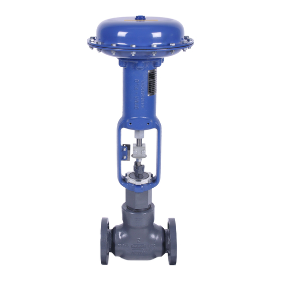
Figure 1 Model DFC
Actuator and DF2000 Valve
Dyna-Flo DFC
Operation, Parts and Instruction Manual
Table of Contents
Actuator Specifictions
Unpacking Actuator
Rigging Set Up Diagram
Bench Setting
Bench Setting Diagram
Mounting
Yoke Nut Tightening Diagram
Maintenance
Dyna-Flo Control Valve Services Ltd.
Edmonton, Alberta, CANADA
Website: www.dynaflo.com
M od el
DF C
Valve Actuator
O p e ra t io n, Pa r t s a nd I ns t r uc t io n Ma n ua ls
3
4
4
4
5
5
6
7
Phone: 780
Toll Free: 1
Fax: 780
Actuator Disassembly
Actuator Assembly
Actuator Mounting Diagram
Torque Chart
DFC Diaphragm Plate Diagram
Actuator Cross Section
Parts List
Model Builder
469
4000
•
•
866
396
2356
•
•
•
469
4035
•
•
7
8
9
11
11
12
14
20
1
Advertisement

Related Manuals for Dyna-Flo DFC

Summary of Contents for Dyna-Flo DFC
- Page 1 DF C Valve Actuator O p e ra t io n, Pa r t s a nd I ns t r uc t io n Ma n ua ls Figure 1 Model DFC Actuator and DF2000 Valve Dyna-Flo DFC Operation, Parts and Instruction Manual Table of Contents Actuator Specifictions...
- Page 2 When combined with a Dyna-Flo Model DF2000 or 360 control valve, the DFC is part of a rugged control valve assembly, to which a wide variety of controllers and instruments can be attached.
- Page 3 Capabilities NOTES: 1 These values also apply to the DFC Size 3220-4 actuator. 2 Actuator travel may be less than the value listed after connected to the valve. 3 Maximum actuator travel for the 3220-4 is 4 inches (102 mm).
- Page 4 (Key 22) between the actuator stem (Key 3) and the valve stem (Key 31). Except for the DFC Size 3220, the stem Figure 2 Rigging Setup connector assembly (Key 22) will need to be installed to prevent the stem from rotating while adjusting the bench set.
- Page 5 5 Psi (34 kPa) to the actuator and note incorrect or damaged spring may be the where stem travel stops, this should occur problem. Contact your Dyna-Flo Sales when the travel stop (Key 10) encounters the Office for more information.
- Page 6 Figure 4 Yoke Nut Tightening Stem Connector Installation Apply upper loading pressure plus 5 Psi (34 kPa) to the actuator if loading pressure was not applied prior to mounting. This should put the Dyna-Flo Control Valve Services Ltd. Phone: 780 4000 • •...
- Page 7 Using a pair of pliers or other tool, remove the actuator is secured in place and properly snap ring (Key 14) from the yoke (it sits overtop of the bushing (Key 15). Replace if necessary. supported. Dyna-Flo Control Valve Services Ltd. Phone: 780 4000 • •...
- Page 8 By threading the spring adjuster part (Key 1) (on a DFC size 3220 actuator there is way onto the actuator stem the assembly may an o-ring in place of the gasket). The holes of be inserted up into the yoke and used as a plunger to push out the bushing.
- Page 9 In a circular pattern re-tighten the casing cap screws (Key 18) to full torque. Refer to Bench Setting Actuator portion of manual to complete the actuator assembly. Figure 5 Actuator & Valve Mounting Diagram Dyna-Flo Control Valve Services Ltd. Phone: 780 4000 • •...
- Page 10 For down travel stops relieve any spring pressure or compression before you start the disassembly process, this can be done by lowering the spring adjuster (Key 21). Dyna-Flo Control Valve Services Ltd. Phone: 780 4000 • •...
- Page 11 Figure 6 Model DFC Actuator Cross Section (2 Piece Diaphragm Plate Design) Our Commitment of Quality Dyna-Flo is committed to continuous improvement. All efforts have been taken to maximize the accuracy of this information. Without notification, product specifications and designs may be modified at any time. The issue of this document is for information only, and does not imply suitability, a warranty, or guarantee for a specific service.
- Page 12 O p e ra t ion , Par t s a nd In s t r u c t io n M a nu a ls * Note: part of valve body assembly. Figure 7 Model DFC Actuator Cross Section Dyna-Flo Control Valve Services Ltd. Phone: 780 4000 •...
- Page 13 O p e ra t io n, Pa r t s a nd I ns t r uc t io n Ma n ua ls TYPE 3 DOWN STOP DFC TYPE 4 UP STOP DFC TYPE 5 UP STOP DFC Figure 8 Model DFC Actuator Cross Section Dyna-Flo Control Valve Services Ltd. Phone: 780 4000 • • Toll Free: 1 2356 •...
- Page 14 Size 2156 & 3156 H5FZ38.100 Size 2156 & 3156 2E84751904D (Qty. 24) Size 3220 2N12701904D Size 3220 H5FZ38.114 (Qty. 28) Dyna-Flo Control Valve Services Ltd. Phone: 780 4000 • • Toll Free: 1 2356 Edmonton, Alberta, CANADA • • •...
- Page 15 Size 3105 & 3156 1E83283899D Steel (See Table 5, Page 19) Size 3220 1B97183899D Stem Nut Steel Pl. Size 1069 1P13122414D Dyna-Flo Control Valve Services Ltd. Phone: 780 4000 • • Toll Free: 1 2356 • • • Edmonton, Alberta, CANADA...
- Page 16 Size 1069, 2069, 2105, 1A36842405D 2156, 3105, 3156 Size 3220 1N12932899D Type 4 Size 1069, 2069, 2105 1A36842405D 2105, 2156, 3105, 3156 Dyna-Flo Control Valve Services Ltd. Phone: 780 4000 • • Toll Free: 1 2356 Edmonton, Alberta, CANADA •...
- Page 17 3220 1-1/2 (38) 1R4098X002D 1R41142409D 1H74593899D 2 (51) 1R4099X002D 1R41132409D 1H74603899D 3 (76) 1R4102X001D 1R41072409D 1H74613899D Dyna-Flo Control Valve Services Ltd. Phone: 780 4000 • • Toll Free: 1 2356 • • • Edmonton, Alberta, CANADA Fax: 780 4035 •...
- Page 18 (yellow) (red) 2 (51) 1N12842708D 1N12852708D (light green) (light blue) 3 (76) 1N12862708D 1N12872708D (dark grey) (yellow) Dyna-Flo Control Valve Services Ltd. Phone: 780 4000 • • Toll Free: 1 2356 Edmonton, Alberta, CANADA • • • Fax: 780 4035 •...
- Page 19 3220 1-1/2 (38) 1N12902409D (Qty: 3) 2 (51) 1N12914092D (Qty: 3) 3 (76) 1N12922409D (Qty: 3) 3220-4 4 (102) 11A8131X01D (Qty: 3) Dyna-Flo Control Valve Services Ltd. Phone: 780 4000 • • Toll Free: 1 2356 • • • Edmonton, Alberta, CANADA...
- Page 20 Valve Actuator O p e ra t ion , Par t s a nd In s t r u c t io n M a nu a ls Dyna-Flo DFC / DFO Series Actuators | Model Numbering System Sample Part Number...
Need help?
Do you have a question about the DFC and is the answer not in the manual?
Questions and answers