Advertisement
Quick Links
Advertisement

Related Manuals for CommBox CFP700


Summary of Contents for CommBox CFP700
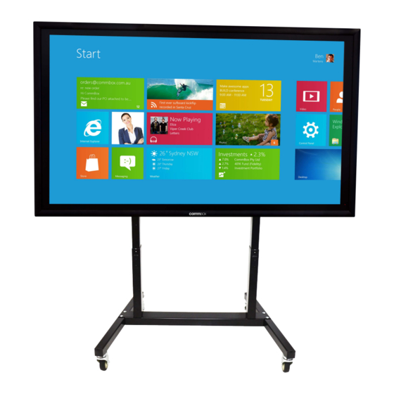
- Page 1 CFP700 Instruction Guide including CFP701 Accessory Kit CFP702 Z Brackets...
- Page 2 Step 1: Legs, Remove the Castors from the forks. Using 4x 12x30mm bolts and nylock nuts secure the castors to parts 431 ensuring the lockable castors go on the short end (rear). Replace the castors into the forks and hammer the End Caps in position.
- Page 3 Step 2: Base, Using 4x 8x65 Cup Head Bolts and nylock nuts secure part 972 to the legs as shown. Note: the lockable castors are at the thin end (Rear). Step 3: Locking bars, Using 2x 6x12mm Socket Head Cap Screws, nylock nuts and 4x small 6mm washers, secure the screws into parts 968 as show.
- Page 4 Step 4: Tilt Brackets 969/971. Using 8x 6mm Socket Head Cap Screws and nylock nuts secure the locking bars to parts 969 and 971 as shown. Step 5: Tilt brackets to 970 brackets. Using 2x 10x20mm bolts, 2x 10mm washers and nylock nuts secure the tilt brackets 969 &...
- Page 5 Step 6: Cable Tray 973, 970 brackets to Actuators. Place the rear of the actuator on a flat surface. Orientate part 973 so the front is upper most. And the actuators are sitting in either end. Slid parts 970 in from each end between 973 and the actuator. Using 8x 6mm Cap Screws secure these parts in place Step 7: Using a minimum of two...
- Page 6 Step 8: Laptop Tray, Control Box and Power board. Using 1x 6mm Cap Screw and nylock nut secure this end of the laptop tray. From the bottom hold the control box up and line up the holes in part 973 sandwiching the Laptop Tray between parts 973 and the control box.
- Page 7 Step 9: VESA Rails, Using 8x 8x12mm bolts and nylock nuts secure the top part 974 into position as shown.. Then loosely secure the bottom part 974 into position it should be able to freely move within the slots this part will be secured after the panel is in place.
- Page 8 Step 11: Using 4x 4x8mm screws and nylock nuts secure the LED controller to the top of part 971. Run the lead down the back of part 971 and into part 973 and down through into the control box. The LED controller bracket angle can be adjusted to suit the individual requirements.
- Page 9 Step 14: Mounting the panel, Note: Panels over 75’’ in size will not work with this product. Lower the trolley to it’s lowest setting and tilt the frame to the horizontal position. Using a minimum of two people (preferably four) lift the panel onto the trolley. Then from the bottom secure the panel to the trolley using 4x 8x20mm bolts.
- Page 10 Step 16: Cover plates 437, Push up and bend the LED control panel bracket for clearance for part 437 Using 4x 6x12mm cap screws two per side secure parts 437 to the rear of parts 969 and 971 as shown. Cycle the trolley Up/Down including tilting to table to ensure nothing fowls on any of the moving parts during the travel cycles.
Need help?
Do you have a question about the CFP700 and is the answer not in the manual?
Questions and answers