
Related Manuals for Grace Q-Zone Hoop-Frame PRO


Summary of Contents for Grace Q-Zone Hoop-Frame PRO
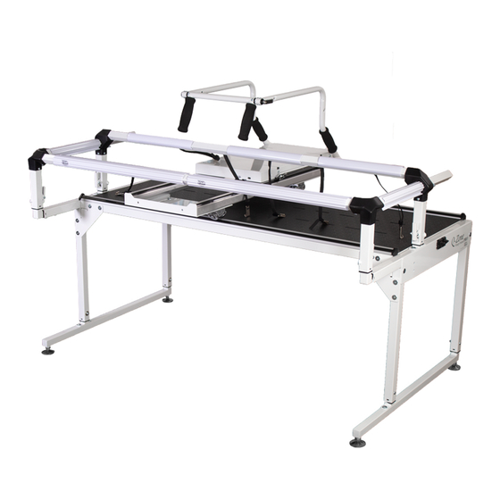
- Page 1 Hoop-Frame Assembly Instructions Copyright October 19, 2020 Grace Company (Reproduction Prohibited) Version 1.1 US Patent 9476151...
-
Page 2: Table Of Contents
Table of Contents Table of Contents ........................i Parts List Box 1 ............................ii Box 2 ............................iii Box 3 ............................iv Assembly Instructions Step 1: Right Leg Setup ....................... 1 Step 2: Left Leg Setup ......................... 3 Step 3: Frame Cross Support Installation ..................5 Step 4: Front Long Rail Installation .................... -
Page 3: Parts List
Part List Box 1 Left Leg Assembly (1) Right Leg Assembly (1) Corner Brace (4) Bungee Mount (4) M6 x 10mm Connector (QZF-04-12031) (SVP-05-13306) Bolt (16) (HDW-03-10953) Bungee Clamp Side Fabric Clip (2) Assembly (4) (QZF-05-12024) (ACC-01-10261) -
Page 4: Box 2
Parts List Box 1 - Continued 4mm Allen Wrench (1) 10mm & 13mm Box 14mm & 17mm Box 3mm Allen Wrench (1) (HDW-03-10167) End Wrench (1) End Wrench (1) (HDW-03-10166) (HDW-03-10743) (HDW-03-12068) Hoop Frame Leader Cloth Set (1) (ACC-01-13370) Box 2 Front Fabric Clip (2) Fabric Clip (3) (QZF-05-12025) -
Page 5: Box 3
Parts List Box 3 Carriage (1) (CNT-09-11866) Channel Lock (2) Channel Lock M6 x 20mm (ACC-09-13057) Washer (2) SBHCS (2) (CNT-04-11580) (HDW-03-10088) -
Page 6: Step 1: Right Leg Setup
Assembly Step 1 – Right Leg Setup Parts Needed: Right Leg Corner Brace (2) Assembly (1) 3mm Allen M6 x 10mm Wrench Screws M6 x 10mm Connector Bolt (4) Tools Needed: 3mm Allen Wrench 1-1 Loosen the (2) M6 x 10 Set Screws. 4mm Allen Wrench 10mm &... - Page 7 Assembly Hole Floor to Top of Number Fabric 31 Inches 32 Inches 33 Inches 34 Inches 35 Inches 36 Inches 37 Inches 38 Inches 39 Inches Hole 40 Inches Number 1 1-4 Adjust table height by sliding legs up or down Note: Height will vary slightly after adjusting using the chart to the right for your desired height.
-
Page 8: Step 2: Left Leg Setup
Assembly Step 2 – Left Leg Setup Parts Needed: Left Leg Corner Brace (2) Assembly (1) M6 x 10mm M6 x 10mm 3mm Allen Connector Bolt (4) Wrench Screws Tools Needed: 3mm Allen Wrench 2-1 Loosen the (2) M6 x 10 Set Screws. 4mm Allen Wrench 10mm &... - Page 9 Assembly Hole Floor to Top of Number Fabric 31 Inches 32 Inches 33 Inches 34 Inches 35 Inches 36 Inches 37 Inches 38 Inches Hole 39 Inches Number 1 40 Inches 2-4 Adjust table height by sliding legs up or down Note: Height will vary slightly after adjusting using the chart to the right for your desired height.
-
Page 10: Step 3: Frame Cross Support Installation
Assembly Step 3 – Frame Cross Support Installation Parts Needed: Table Assembly M6 x 10mm Table Assembly (1) Connector Bolt (8) Tools Needed: M6 x 10mm 4mm Allen Wrench Connector Bolt 3-1 Install the Table Assembly to the Right Leg using (4) M6 x 10mm Connector Bolts by angling the Table Assembly toward the ground. -
Page 11: Step 4: Front Long Rail Installation
Assembly Step 4 - Front Long Rail Installation Parts Needed: Front Corner Front Long Rail (1) M6 x 40mm SBHCS Tools Needed: 4mm Allen Wrench 4-1 Remove the (2) M6 x 40mm SBHCS from the Right Front Corner. Front Corners Front Long Rail Large Holes Front Corner... -
Page 12: Step 5: Carriage Assembly
Assembly Step 5 - Carriage Assembly Parts Needed: Carriage (1) Channel Lock (1) Wheel M6 x 16mm SBHCS Channel Lock M6 x 20mm SBHCS Washer (1) Tools Needed: 5-1 Remove the right rear M6 x 16mm SBHCS and 4mm Allen Wrench Wheel from the Carriage. -
Page 13: Step 6: Carriage Installation
Assembly Step 6 - Carriage Installation Tools Needed: 4mm Allen Wrench M6 Connector Bolt Bottom View 6-1 Place the Carriage onto the Track. 6-2 Loosen the (4) M6 Connector Bolts for the Note: Make sure the Channel Lock is in the open Back Track Assembly. -
Page 14: Step 7: Back Long Rail Installation
Assembly Step 7 - Back Long Rail Installation Parts Needed: M6 x 30mm Thumb Screws Back Long Rail (1) Back Corner Right Tools Needed: Cover 4mm Allen Wrench STOP: Follow quilting machine manual for instructions on preparing and installing the machine before 7-1 Remove the (6) M6 x 30mm Thumb Screws continuuing. -
Page 15: Step 8: Basic Setup
Setup Step 8 - Basic Setup Parts Needed: Bungee Mount (4) Tools Needed: Leveling Foot 3mm Allen Wrench 10mm/13mm Box End Wrench Lower table 14mm/17mm Box End Wrench Raise table 8-1 Adjust the Leveling Feet to level the frame and make sure it is stable. - Page 16 Setup 4mm Hex 8-4 Rotate the Channel Lock handle down. To adjust the Channel Lock, loosen the 4mm upper Hex Nut. Twist the Rubber Foot clockwise until it is snug against the track. Turn the 4mm upper Hex Nut counterclockwise until it is snug against the Channel Lock barrel. Note: Channel Locks are used to lock the Top Plate or the Carriage to assist in straight line stitching.
-
Page 17: Step 9: Fabric Setup
Fabric Setup Step 9 - Fabric Setup Tools Needed: Pins (not included) Fabric (not included) Quilt Top Tape Measure (not included) Fabric Cutting Tools (not included) 9-1 Measure the length and width of your quilt top. Backing 4-5” Batting Batting 2-3”... -
Page 18: Step 10: Fabric Installation
Step 10 - Fabric Installation Parts Needed: Bungee Clamp Fabric Clip (3) Front Fabric Clip (2) Side Fabric Clip (2) Assembly (4) Bungee Stop (4) Leader Cloth Set 10-1 Find the center on your Back Rail Cloth Leader and Front Rail Cloth Leader and mark it. Find the center on your Backing on both the top and bottom edges. - Page 19 Fabric Setup 10-6 Install the (3) Fabric Clip. Pull Fabric snug and install the (2) Front Fabric Clips and (2) Side Fabric Clips. Rotate the Fabric Clips clockwise to tighten the fabric. Side Fabric Clip Fabric Holder Assembly Bungee Rolled Fabric Mount Bungee Mount Holder...
- Page 20 Fabric Setup Bungee Clamp Bungee Clamp Stop 10-9 Insert the Bungee Clamp Cord through the Bungee Mount and the Bungee Stop. Note: See Bungee Clamp instructions for attaching to fabric.
-
Page 21: Care And Use
Care and Use Quilting Tips: - Be Careful not to sew too close to the edge, to prevent hitting the Bungee Clamps, or running off the edge of the quilt. Also, if you are using side leaders, avoid accidentally stitching the leader to your quilt. - If your quilt will fit onto your frame length-wise attach your quilt’s fabric to the rails along it’s length. -
Page 22: Making Leader Cloths
This will be the line to which you attach your fabric layer. 7: Center your cloth leader lengthwise along the rail. Using Grace’s Fabri-FastTM System, take a piece of plastic tubing (cut to the appropriate length), and, holding your cloth leader to the slot (lining up the dashed line), press the tubing over the leader and into the slot. -
Page 23: Top Plate Assembly - Optional Accessory
Assembly Top Plate Assembly - Optional Accessory Parts Needed: Handle Crossbar Handle Left (1) Handle Right (1) Top Plate (1) M6 x 20mm SBHCS Carriage Bolt and M6 x 10mm SBHCS Channel Lock (1) Clamp (1) Tools Needed: 4mm Allen Wrench M6 x 10mm SBHCS (4) 1 Attach Handles using (4) M6 x 10mm SBHCS. - Page 24 Assembly Note: The Carriage Bolt may need to be twisted to pass through both handles. Handle Crossbar Note: May need Carriage Bolt to loosen screws in cross brace to get carriage bolt through, Clamp then retighten screws. 2 Un-thread Clamp from Carriage Bolt. 3 Assemble Cross Brace with the Handle Crossbar, Carriage Bolt, and Clamp.
- Page 25 Assembly Top Plate & Machine Installation - Optional Accessory Parts Needed: Sewing Machine Clamp (4) Top Plate Sewing Machine Top Plate Carriage 1 Place the Top Plate on the Carriage 2 Place the Sewing Machine onto the Top Plate.
- Page 26 Clamp 3 Center Machine on Top Plate from side to side and make the back of the throat of Sewing Machine line up with the vertical part of the handles. Slide each Clamp into the grooves on the Top Plate and lock against Machine.
- Page 27 Notes...
- Page 28 The Grace Company 2225 South 3200 West Salt Lake City, UT 84119 Phone: 1-800-264-0644 Fax: 801-908-8888...
Need help?
Do you have a question about the Q-Zone Hoop-Frame PRO and is the answer not in the manual?
Questions and answers