
Related Manuals for ATIM Atim Cloud Wireless ACW/LW8-TCR

Summary of Contents for ATIM Atim Cloud Wireless ACW/LW8-TCR
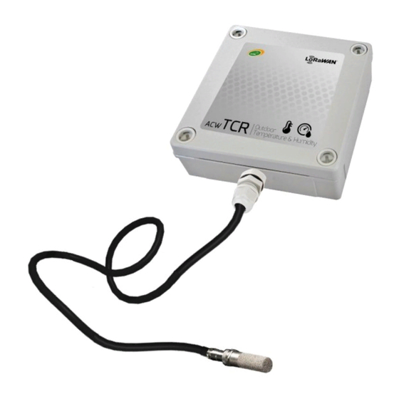
- Page 1 Atim Cloud Wireless Temperature & humidity monitoring Cold room User Guide Modèles concernés : ACW/LW8-TCR ACW/SF8-TCR ATIM Radiocommunications www.atim.com Chemin des Guillets info@atim.com 38250 Villard de Lans France...
-
Page 2: Table Of Contents
Table of contents DOCUMENT VERSION HISTORY ..............................4 DISCLAIMER ....................................4 TRADEMARKS AND COPYRIGHT ..............................4 DECLARATION OF COMPLIANCE ..............................5 ENVIRONMENTAL RECOMMENDATIONS ............................ 5 ................................5 XPLOSIVE ENVIRONMENT ................................... 5 NVIRONMENT ...................................... 6 ADIO TECHNICAL SPECIFICATIONS ............................... 7 ....................................7 RODUCT ’... - Page 3 Alert frame measurement ................................ 27 DOWNLINK ....................................28 .) ..............28 ONFIGURATION OF THE FRAME PARAMETERS SENDING PERIOD NUMBER OF SAMPLES ..............................28 IRTUAL PROBE CONFIGURATION .................................. 29 UMBER OF PROBES ..............................29 HRESHOLD CONFIGURATION ..........................30 ESERVED CODES FOR FUTURES EVOLUTIONS TECHNICAL SUPPORT ................................
-
Page 4: Document Version History
ATIM. Trademarks and copyright ATIM, ACW ATIM Cloud Wireless and ARM Advanced Radio Modem are registered trademarks of ATIM SARL in ® ® France. The other trademarks mentioned in this document are the property of their respective owners. -
Page 5: Declaration Of Compliance
Declaration of compliance All ACW Atim Cloud Wireless products comply with the regulatory requirements of the R&TTE Directive ® (1999/5/EC), article 3: 1 SAFETY (Article 3.1a of the 1999/5/EC Directive) NF EN60950-1 Ed. 2006/A1:2010/A11:2009/A12:2011 (health) EN62479: 2010 (power <20mW) or EN62311:2008 (power > 20mW) 2 Electromagnetic Compatibility (Article 3.1b of the 1999/5/EC Directive) -
Page 6: Radio
General hazard – Failure to follow the instructions presents a risk of equipment damage. Electrical hazard – Failure to follow the instructions presents a risk of electrocution and physical injury. WARNING: do not install this equipment near any source of heat or any source of humidity. WARNING: for your safety, it is essential that this equipment be switched off and disconnected from mains power before carrying out any technical operation on it. -
Page 7: Technical Specifications
Technical specifications a. Product Dimensions 100 x 100 x 35 mm Antenna Integrated (¼ of wave) Temperature probes 1 digital temperature and humidity probe (SHT35) -40°C à +125°C (operating) Temperature -40°C à +150°C (storage) Mounts to Wall, tube or mast, DIN-Rail Casing IP 65 Power Supply... -
Page 8: Housing
Housing a. Space requirements b. Installation ACW-THO modems are fixed to a flat wall using the 4 fixing holes available at each corner of the case. Install the modem at a minimum height of 2m and not glued to the wall, ideally offset at least 20cm Cables must not exceed 10m in length and must be shielded. - Page 9 For best results, it is advisable to place it high up and free from any metallic obstacle within a radius of 1 meter if possible (see figures below). For information, the antenna is integrated into the box. ATIM_ACW-TCR_UG_EN_V1.0...
-
Page 10: Identification
c. Identification The Sigfox or LoRaWAN product identifier is visible on the exterior label on the back of the device, on the electronic card inside and in the status bar in the ACW configuration tool. For LoRaWAN modems, the communication keys are automatically provided by the network (pairing via ‘Over The Air Activation’, or OTAA). -
Page 11: Operating
Operating a. Operating mode The operating of the ACW-TCR deals with several modes: Exploitation mode: this is the default mode when starting the product. In this mode, the module periodically sends measurements according to the configuration applied (if the product has never been configured, the factory configuration applies, cf. -
Page 12: Product Start Up
b. Product start up In most cases, the ACW-TCR is started up before delivery (battery packs already connected) and then placed in deep standby to limit consumption. To place the product in its operating mode, bring a magnet close to the diamond-shaped marking on the box for 6 seconds. -
Page 13: Threshold Exceeded
f. Threshold exceeded When thresholds have been configured using the configurator and the measurement values exceed these thresholds, the product LED emits a periodic ORANGE flash to notify it. g. Anti-fraud system A mechanism (push button) is present on the product to notify any opening of the case during normal operation. Normally, the box exerts pressure on the button. -
Page 14: Acw Configurator
V5.1.0 or greater LoRaWAN: V0.0.1 Download and install the configuration software setup “setupACW.exe” at: https://www.atim.com/en/downloading/ When the ACW Configurator is launched, the waiting Click on "Help" at the top left of the window then on window appears on the screen. -
Page 15: Configuration Du Acw-Tcr
b. Configuration du ACW-TCR Emission period and samples in the frame The transmission period (1) corresponds to the time interval between each sending of a measurement frame. This period can be configured from 10 min to 255 h and its default value is 1 hour. In addition, it is possible to configure the number of samples in a frame (2). -
Page 16: Frame Timestamp
Frame timestamp It is possible to enable / disable the timestamp in all radio frames (5). WARNING: This option when activated monopolizes 4 bytes in the frame which cannot be used for useful data. Product’s clock Each time you connect to the configurator, the product clock is updated (based on the computer clock) and displayed (6). -
Page 17: Factory Settings
c. Factory settings Radio frame settings Emission period of a radio frame: 10 minutes Number of samplings: 1 History depth: 1 General settings Emission period of the keep alive frame: 4 days Timestamp: disabled Sensor’s configuration Probe 1 (physical) State: enabled Threshold: disabled Probe 2 (virtual): State: enabled... -
Page 18: Update Acws
d. Update ACWs When connected with Bluetooth Low Energy to the product, it is possible to update the different software that composes it. To do this, go to the menu Tools->Updater (CTRL+U ATIM_ACW-TCR_UG_EN_V1.0... -
Page 19: Frames' Format
Frames’ format a. Sigfox & LoRaWAN Uplink frame Byte 1 Byte 2 . . . Byte n Frame header Frame specific data We can differentiate three types of frames: ⚫ Classic frame; New generation: Very similar to the old frames, the difference is that you can activate the timestamp. -
Page 20: The Different Type Of Frames
The different type of frames Type of frame Data size Descriptions 0x00 Reserved 0x01 4 bytes Keep alive frame 0x02 0 bytes Downlink request for network testing 0x03 Reserved 0x04 Reserved 0x05 1 byte Teste frame with counter 0x06 Variable (Cfg box) Answer to a configuration frame 0x07 Variable... -
Page 21: Alert Frame
The possible measure types are: Measure type Units Data size Data type Description Temperature in hundredth of a degree Celsius 0x08 c°C 2 bytes (Big Endian - Signed integer ➢ MSB) Resolution: 0.01°C ➢ Max value: 125°C ➢ Min value: -40°C 0x09 2 bytes (Big Endian - Signed integer... -
Page 22: Keep-Alive Frame
These values are defined as follows: Value Description 0x00 Return in the comfort zone Upper threshold crossing 0x01 0x02 Lower threshold crossing 0x03 Reserved The measurement type field here is identical to that of the measurement frame (i.e. 0x08 or 0x09 in hexadecimal for the ACW-TCR). - Page 23 For each error message, a header is inserted and is formed as follows: Error frame header Bit7 Bit6 Bit5 Bit4 Bit3 Bit2 Bit1 Bit0 Message index Length of the error frame The message index field is used to prioritize messages when several errors occur. The length of the error message field indicates the size in bytes of the error message.
- Page 24 0x99 ERR_SENSORS_TIMEOUT A timeout has been reached out on the sensor 0x9A ERR_SENSOR_STOP The sensor did not report a value after reading 0x9B ERR_SENSORS_FAIL The sensor has stopped to operate 0x9C ERR_BOX_OPENED Casing opening 0x9D ERR_BOX_CLOSED Casing closing Only codes 0x8A and 0x95 are followed by additional data corresponding to the battery level in millivolts. This value is coded in two bytes, the most significant byte first (MSB).
-
Page 25: Frames' Examples
b. Frames’ examples Measurement frame With timestamp disabled, no historic and 1 sample: Byte Byte Byte Byte 1 Byte 2 Byte 3 Byte 4 Byte 5 Byte 6 Byte 7 Byte 8 Byte 9 Byte 11 0x19 0xA0 0x08 0x18 (new generation 0x09... - Page 26 Now with 2 samples: Byte 1 Byte 2 Byte 4 Byte Byte Byte Byte Byte 9 Byte Byte Byte Byte Byte 14 Byte Byte Byte Byte Byte 19 Byte Byte Byte Byte 0xA1 0x003 0x08 0x01 0x2C 0x08 0xA4 0x09 0x22 0x13 0x17...
-
Page 27: Alert Frame Measurement
Alert frame measurement For a high threshold exceeded on channel 1 (virtual probe), the frame will be: Byte 1 Byte 2 Byte 3 Byte 4 0x8D 0x58 0x02 0xC9 (new generation alert frame) high threshold channel 1 exceeded, temperature measurement) The sample which has trigged the alert is 0x02C9 (7.13 °C) ATIM_ACW-TCR_UG_EN_V1.0... -
Page 28: Downlink
The operation of the Downlink is explained in the document ATIM_ACW-DLConfig_UG_EN_v1.4, relating to version V1.2.0 of the ATIM Downlink Protocol (see this document for all parameters and commands common to all products). The parameters specific to ACW-TCR are as follows: a. -
Page 29: Number Of Probes
c. Number of probes Parameter code(Byte 1) Parameter value (Byte 2) 0x17 0x00 = No probes enabled 0x01 = only physical probe is enabled 0x11 = both probes are enabled Note: The value 0x10 is not possible because the virtual probe requires value from physical probe. d. -
Page 30: Reserved Codes For Futures Evolutions
e. Reserved codes for futures evolutions Parameter code (Byte 1) Parameter value (Byte 2) 0x10 0x08 0x11 0x00 WARNING: DO NOT CHANGE THESE VALUES ATIM_ACW-TCR_UG_EN_V1.0... -
Page 31: Technical Support
Technical support Contact our technical support team by email with any questions or technical problems you may have: https://www.atim.com/en/technical-support/ ATIM_ACW-TCR_UG_EN_V1.0...
Need help?
Do you have a question about the Atim Cloud Wireless ACW/LW8-TCR and is the answer not in the manual?
Questions and answers