Advertisement
Quick Links
1
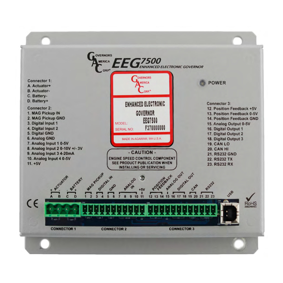
INTRODUCTION
GAC's EEG7500 enhanced electronic governor is designed to regulate engine speed
on diesel and gaseous fueled engines. When paired with a GAC actuator the EEG is
a suitable upgrade for any mechanical governor system that needs flexibility, preci-
sion, or accurate control of governed speed. The EEG7500 is designed for industrial
engine applications from generator sets, mechanical drives, pumps, and compressors
to off-road mobile equipment. Configuring is easy with GAC's free
software. The EEG7500 supports:
Flexible actuator compatibility including bidirectional actuators with or without
Š
actuator position feedback signal, bi-directional torque motors, and Bosch-style
throttle bodies.
Fully configurable digital and analog inputs and outputs
Š
Inputs: 5 analog, 2 digital
Š
Outputs: 1 analog, 3 digital
Š
0 - 5 V DC, 4 - 20 mA, 0 - 10 V DC, or ±3 V DC input ranges
Š
Speed Sync using CAN bus
Š
Virtual Input/Output Routing
Š
Feedback Speed Control Mode
Š
Variable Speed Capability
Š
Fuel Curve Shaping
Š
EEG7500 supports three
operating
Non-Feedback Speed Control (NFSC) provides standard
Š
feedback sensor is required. PID (Proportional, Integral, Derivative) governor functions are optimized for best response and control
of the requested engine revolutions per minute (rpm).
Feedback Speed Control (FSC) combines NFSC and PM modes for use with proportional or bidirectional (torque motor) actuators. A
Š
position feedback sensor is required. The Speed PID position request is the input to the Positioner loop, the Position PID optimizes
response and control of the requested actuator position.
Positioner Control (PC) (uncommon) provides actuator positioning control and is used with proportional actuators or bidirectional
Š
(torque motor) actuators with a feedback sensor (required).
2
EEG7500 SPECIFICATIONS
Performance
Isochronous Operation
Governed Speed /
Sensor Frequency Range
Droop Range
comPLIance / STanDarDS
Agency
Communications
PHYSIcaL
Dimension
Weight
Mounting
reLIaBILITY
Vibration
Shock
Testing
LeD
Solid Green
Blinking Green
Unlit
Enhanced Electronic Governor
modes:
100 Hz - 12 kHz
Up to 25 % regulation
CE and RoHS Requirements
USB, RS-232-C, SAE J1939
See
Section
3,
Controller Installation
18.4 oz [0.52 kgf]
Any position, vertical preferred
10 - 2000 Hz @ 7 g, per SAE J1455
20 g, 11 ms per SAE J1455
100 % Functional Testing
Ready. Controller is powered on.
Warning. Engine service due, or other. Dis-
played in GAConfig Tool System Status.
EEG7500
GAConfig Tool
PID
governing function for use with proportional actuators. No position
InPUT / oUTPUT
Supply
± 0.25 %
Polarity
Power Consumption
Speed Sensor Signal Input
Actuator Output
Load Share /
Synchronizer Input
Reverse Power Protection
Transient Voltage Protection
Digital Switch Output(s)
envIronmenTaL
Ambient Temperature
Relative Humidity
Salt Spray
All Surface Finishes
No power.
1
12 - 24 V DC Battery systems
Negative Ground (Case Isolated)
200 mA continuous plus actuator current
400 mA with excitation at MAX load current
0 - 10 V DC (5 V Nominal, Selectable
Polarity, 145 Hz / V Sensitivity)
Protected to -40 V DC
-40 to 180 °F [-40 to 85 °C]
up to 90 % Non-Condensing
at 38 °C [100 °F] (per SAE J1455)
Fungus Proof and Corrosion Resistant
EEG7500 Enhanced Electric Governor 8-2021-A8
Governors America Corp. © 2021 Copyright All Rights Reserved
(6.5 to 32 V DC)
1.0 - 60.0 V RMS
10 A Continuous
±
or 0 V
3 V DC
60 V DC
Rated to 2 A DC
ASTM B117
PIB5115
Advertisement

Related Manuals for GAC EEG7500

Summary of Contents for GAC EEG7500
- Page 1 INTRODUCTION GAC’s EEG7500 enhanced electronic governor is designed to regulate engine speed on diesel and gaseous fueled engines. When paired with a GAC actuator the EEG is a suitable upgrade for any mechanical governor system that needs flexibility, preci- sion, or accurate control of governed speed. The EEG7500 is designed for industrial engine applications from generator sets, mechanical drives, pumps, and compressors to off-road mobile equipment.
- Page 2 Do not rely exclusively on the governor system electronic actuator to prevent overspeed. A secondary shutoff device, such as a fuel solenoid must be used. GAConfig Tool shuts down fuel to the actuator, but does not directly shutdown the engine. eeG7500 connecTorS The following connectors are required when using the EEG7500. ITem no. ParT nUmBer...
- Page 3 EEG7500 WIRING DIAGRAMS Wire the EEG7500 for either speed control position control, detailed in this sections following figures. Items highlighted in the following table are the minimum connections required before starting. Read this entire manual before starting. Determine what hardware devices will be involved in the installation and ensure you know where they are being mapped to on this speed controller.
- Page 4 EEG7500 WIRING DIAGRAMS (CONTINUED) WIrInG for feeDBack SPeeD conTroL anD non-feeDBack SPeeD conTroL moDe EEG7500 Enhanced Electric Governor 8-2021-A8 PIB5115 Governors America Corp. © 2021 Copyright All Rights Reserved...
- Page 5 EEG7500 WIRING DIAGRAMS (CONTINUED) WIrInG for PoSITIon conTroL EEG7500 Enhanced Electric Governor 8-2021-A8 PIB5115 Governors America Corp. © 2021 Copyright All Rights Reserved...
- Page 6 Speed sensor voltage should be at least 1 V AC RMS during crank. If the EEG7500 detects no input from the magnetic (mag) pickup, the EEG will set the actuator to 0 V DC and set the speed to 0 rpm.
- Page 7 The auxiliary (AUX) terminal accepts input signals from load sharing units, auto synchronizers, and other governor system accessories. The AUX input enables or disables the load sync input. GAC accessories connect directly to this terminal. The AUX function decreases engine speed in response to increased input voltage.
- Page 8 The tool also allows you to set up multiple scenarios and save them for use later or for sharing with other sites-solutions using the EEG7500. The GAConfig Tool is downloaded from GAC’s website. The following is required to run the software: •...
- Page 9 The zip file is saved in the PCs default download area, unless you tell it otherwise. Once downloaded, double-click the file name to start the instal- lation. You may need to double click again on the EEG7500 IT setup.exe file to actually begin the installation.
- Page 10 GAConfig Tool using engine voltage. TooL Bar The tool bar provides access to connect to your EEG7500, use imported and exported configuration files, create and save data plots, view setting history, view error logs, or reset your current settings.
- Page 11 Fixed position Š Variable position Š Position Speed Settings Š Position Feedback Setup Š Position Control Table Š EEG7500 Enhanced Electric Governor 8-2021-A8 PIB5115 Governors America Corp. © 2021 Copyright All Rights Reserved...
- Page 12 I/o confIGUraTIon I / O Configuration maps physical input and output connections between the EEG7500 controller, the engine, and other hardware. Physical Input mapping allows you to choose from 15 options to relate that terminal to a hardware device. For example: A potentiometer is wired at Terminal 7 (Analog In) on the EEG7500 controller to support Variable Speed Š...
- Page 13 INITIAl SYSTEM SETUP The EEG7500 can be set up and used out of the box, with an actuator attached, using default settings. Default settings are shown in section 17, Default Configuration. This section details the initial installation and setup using the default settings. Wiring between the engine and the EEG7500 is required, and reviewing this document and default settings is advised.
- Page 14 DefaULT I / o DevIce maPPInG The EEG7500 controller pairs device input mapping of signals physically connected to the EEG with various input and output parame- ters. The controller supports 5 analog and 2 digital inputs, and 1 analog and 3 digital outputs. Physical inputs are mapped to the param- eter settings in the GAConfig Tool.
- Page 15 Output Mapping lets you assign external signals such as J1939 to specific outbound locations. It is also useful for setting external de- vices to complete tasks based on overspeed or another event. EEG7500 Enhanced Electric Governor 8-2021-A8 PIB5115 Governors America Corp. © 2021 Copyright All Rights Reserved...
- Page 16 Once the control mode for your actuator is selected, the following minimum parameters must be set, or the default settings used, before starting the engine. GAC suggests using the default settings to first ensure the engine runs smoothly before adding additional devices.
- Page 17 GAConfig Tool and a solenoid or other relay switch and complete the following set up. Connect a shutdown solenoid between the engine and an EEG7500 digital terminal. From the GAConfig Tool, open the I/O Configuration menu and set the following: a.
- Page 18 Set the DEADTIME to Low. If instability persists, change DEADTIME to High. Additional adjustments may be required after engine load is applied. Normally adjustments made at no load achieves satisfactory perfor- mance. EEG7500 Enhanced Electric Governor 8-2021-A8 PIB5115 Governors America Corp. © 2021 Copyright All Rights Reserved...
- Page 19 Open Engine Tuning Variable Speed For each variable speed: • Set Gain • Set Speed Maximum and Variable Speed End Gain • Set Stability EEG7500 Enhanced Electric Governor 8-2021-A8 PIB5115 Governors America Corp. © 2021 Copyright All Rights Reserved...
- Page 20 Instead of using physical inputs, you can also check the Override box, and manually set the On or Off state of the selected physical input. The On/Off state stays set even after the EEG7500 is disconnected from PC software. • on equals a closed state •...
- Page 21 Use a potentiometer to make incremental position changes. Wire a potentiometer to the EEG7500 to control the position of the actuator valve. Open the GAConfig Tool. From the Engine Tuning menu, check or change your settings to the following: Select Position Control from the Operating Mode drop-down list.
- Page 22 These inputs require the use of momentary switches. Contact GAC if more information is required. PoSITIoner varIaBLe PoSITIon SeTTInGS 1. Set the selected Speed Mode to Variable by setting Speed Select A...
- Page 23 Best practice is to export GAConfig Tool information on a regular basis, monthly at a minimum. Name the file with dates and intended use as part of the file name. These files can also be shared with the GAC support team to aid in producing the best results.
- Page 24 ADDING lOOkUP TABlES The EEG7500 GAConfig Tool includes the ability to create and store lookup tables for use with Positioner and Fuel Limit functions. The tool lets you create tables that are then selected for use on the Position Tuning or FSC Fuel Limit menus of the GAConfig Tool.
- Page 25 The J1939 is set up through Terminals 19 and 20, and using the GAConfig Tool. The EEG7500 responds to J1939 speed requests with the J1939 speed control taking priority over speeds selected by Speed A and B selections.
- Page 26 Previously active diagnostic trouble- 65227 Diagnostic Message 2 (DM 2) On Request shooting codes. 65228 Diagnostic Message 3 (DM 3) On Request Clear Previously Active Faults EEG7500 Enhanced Electric Governor 8-2021-A8 PIB5115 Governors America Corp. © 2021 Copyright All Rights Reserved...
- Page 27 To save the data, click the Save button. The file is saved as a printable graphic (.png) file. Select Reset Pan to move the cursor on the grid back to start position. EEG7500 Enhanced Electric Governor 8-2021-A8 PIB5115 Governors America Corp. © 2021 Copyright All Rights Reserved...
- Page 28 Light Force Governing On - Off Light Force Governor improves resolution when controlling small and low current actuators including GAC T1 ATB, ALR/ALN, 100/103/104 series and normally closed actuators. Speed Anticipation On - Off Speed anticipation ON reduces rpm recovery time during high load transients and requires both no load (NLCU) and full load current (FLCU) values are entered.
- Page 29 Stability/Integrator of the position loop when in uniform gain mode Auto-Tune Button select Enables and starts the automatic PID calibrations. Valid for FSC and PM modes only. enable Position control Table EEG7500 Enhanced Electric Governor 8-2021-A8 PIB5115 Governors America Corp. © 2021 Copyright All Rights Reserved...
- Page 30 Configures the data source for output 1, 2, or 3. Output data elements may be rout- Digital Output 2 Source Alarm ed to multiple hardware outputs. Digital Output 3 Source Warning Analog Output 1 Source Engine Load EEG7500 Enhanced Electric Governor 8-2021-A8 PIB5115 Governors America Corp. © 2021 Copyright All Rights Reserved...
- Page 31 Analog Output 2 (SPN4165) Source Dropdown Disabled selection Analog Output 3 (SPN4164) Source Dropdown Disabled selection Analog Output 4 (SPN4163) Source Dropdown Disabled selection EEG7500 Enhanced Electric Governor 8-2021-A8 PIB5115 Governors America Corp. © 2021 Copyright All Rights Reserved...
- Page 32 Open the GAConfig Tool. Click Connect. The Select Serial Port window displays. Click Advanced Configuration arrow. Select the number of the com port the EEG7000 is plugged into. If no com ports display call your GAC representative. Check to make sure your baud rate is set to 19200 and all other settings are as show in this example.
- Page 33 What is PID? The EEG7500 is a PID controller. This means it uses a correction algorithm that combined with user added settings for proportional (Gain), integral (Sta- bility) and derivative (dead time) makes the engine more responsive to load changes. Gain (P), Stability (I) and Deadtime (D) settings are individually ad- justed, and based on the difference between these setting values the speed control unit uses the PID algorithm to calculate a correction factor to smooth response times during transient load changes in your engine.
Need help?
Do you have a question about the EEG7500 and is the answer not in the manual?
Questions and answers