
Related Manuals for Net Safety MAN-0069

Summary of Contents for Net Safety MAN-0069
- Page 1 4-20 mA FIRE HEAD with Analog/RS-485 Modbus (AD) CONTROLLER User Manual Part Number: MAN-0069 Rev 2 May 2006...
-
Page 3: Warranty
Contact Net Safety Monitoring Inc., or an authorized representative for details. Safety Monitoring Inc., does not guarantee the results and assumes no We welcome your input at Net Safety Monitoring. If you have any comments obligation or liability. please contact us at the phone/address below or visit our web site and complete No part of this manual may be copied, disseminated or distributed without the our on-line customer survey: www.net-safety.com. -
Page 4: Table Of Contents
Net Safety Monitoring Inc Step 4 — Operate ........7... -
Page 5: Introduction
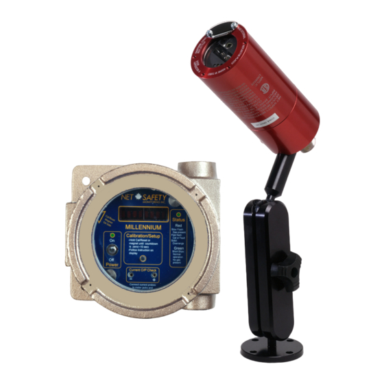
Controller RODUCT 6.84920” 5.5996” Fire Head Net Safety’s 4-20 mA output UV/IRS, UVS, IRS, and Phoenix IR3S fire detector heads can be used in conjunction with the Digital Controller. 4.06” 5.28” The Controller The Controller has an explosion-proof Housing, rated Class 1, Division 1, Groups B, C, and D for hazardous applications. -
Page 6: Step 2 - Install
Net Safety Monitoring Inc. STEP 2 — I NSTALL OCATE ONTROLLER Fire Head NPACK Locate Fire Heads as per the manual provided with the specific product. Carefully remove all components from the packaging. Check components against the enclosed packing list and inspect all components for obvious Controller damage such as broken or loose parts. -
Page 7: Step 3 - Wire
Net Safety Monitoring Inc STEP 3 — W • The jacket and shielding of the cable should be stripped back to permit the seal to form around the individual wires. This will prevent air, gas and water leakage through the inside of the shield and into the enclosure. -
Page 8: Wiring-Controller
Net Safety Monitoring Inc Shielded copper instrument wire (minimum 18 AWG) should be used for — IRING ONTROLLER separations up to 500 feet. Shielded copper instrument wire (minimum 16 AWG) should be used for separations up to 2000 feet. Consult the factory if a WARNING: greater separation distance is required. -
Page 9: Non-Isolated/Isolated Wiring
Net Safety Monitoring Inc Current Output SOLATED SOLATED IRING To set an isolated current output, simply move the Jumper (shorting jack) to Terminal Connection either the isolated or non-isolated current position (refer to Figure 7). Figure 5: Non-isolated Terminal Connection Note: Unless otherwise specified, all models ship with non-Isolated current output. -
Page 10: Modbus Termination
Net Safety Monitoring Inc. MODBUS T ERMINATION Devices are networked in a daisy chain. The device located at the end of the chain requires end of line termination. Place both jumpers over the pins, as shown in Figure 8, for end of line termination. -
Page 11: Step 4 - Operate
Net Safety Monitoring Inc. STEP 4 — O PERATE The Controller faceplate contains most functional elements of the user interface. Below is a description of that functionality. Figure 9: Controller Functionality Scrolling 8-character display - provides various status messages and prompts. -
Page 12: The Main Menu
Turn power switch On. A 90 second warm-up routine will begin. The display to be reviewed and set. Refer to Figure 9 for more information. shows Start Delay Millennium Net Safety, the Status LED is Red • Press and hold the Calibration Button to access Main Menu. -
Page 13: Select Display Language
Net Safety Monitoring Inc Baud Rate ELECT ISPLAY ANGUAGE The transmission speed must be defined. Step 1: Wait for Select Display Language YES? to display. Press the Calibration Button or use the Reed Switch to select. Step 1: When Modbus Setup? YES? displays press the Calibration The flashing YES confirms the selection. -
Page 14: Step 5 - Monitor
Net Safety Monitoring Inc STEP 5 — M ONITOR Table 5: RTU Output Register (40001) Read Only (binary) There are a variety of ways to indicate the status of the connected detectors: current output, LEDs and Display Messages. RTUfire_power_up 0x0001... -
Page 15: Step 6 - Maintain
A Material Return Authorization number is required in order to return Section of the specific Fire Head manual for Fire Head maintenance and testing equipment. Please contact Net Safety Monitoring at (403) 219-0688 before procedures. returning equipment or consult our Service Department to possibly avoid returning equipment. -
Page 16: Face Rotation Option
Net Safety Monitoring Inc Rotate PCB Assembly OTATION PTION 1. Remove the Controller’s Housing Cover. In some applications, it is necessary for the Controller to be mounted in a non- 2. Turn the power to the detector off. standard orientation. To accommodate such installations and ensure that the 3. -
Page 17: Appendix A: Electrostatic Sensitive Device (Esd)
Net Safety Monitoring Inc Appendix D: E (ESD) LECTROSTATIC ENSITIVE EVICE Electrostatic discharge (ESD) is the transfer, between bodies, of an electrostatic charge caused by direct contact or induced by an electrostatic field. The most common cause of ESD is physical contact. Touching an object can —ESD... -
Page 18: Appendix B: Resistance Table (Ohms)
Net Safety Monitoring Inc Appendix E: R ESISTANCE ABLE Distance (Feet) AWG #20 AWG #18 AWG #16 AWG #14 AWG #12 AWG #10 AWG #8 1.02 0.64 0.40 0.25 0.16 0.10 0.06 2.03 1.28 0.80 0.51 0.32 0.20 0.13 3.05 1.92... -
Page 19: Appendix C: Specifications
Net Safety Monitoring Inc. Appendix F: S PECIFICATIONS ONTROLLER PECIFICATION Controller 4-20 mA ANALOG OUTPUT RS-485 MODBUS OUTPUT Operating Temperature Range -40°C to +85°C (-40F to +185F) Fire Head Power Consumption Nominal 170 mA / 4.08 W @ 24 V dc Maximum 230 mA / 5.52 W...