Advertisement
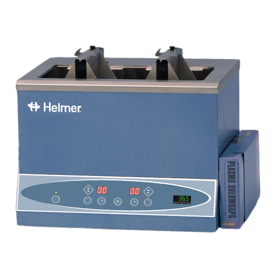
PLASMA THAWING SYSTEM
MODELS DH4 and DH8
VERSION K
Operation – Service - Maintenance
HELMER LABS, INC. 15425 HERRIMAN BLVD., NOBLESVILLE, IN 46060 USA
PHONE (317) 773-9073 FAX (317) 773-9082
USA and CANADA
1-800-743-5637
Contents
PAGE
Installation.......................................................................... 2
1-360008/G
D
Advertisement
Table of Contents

Related Manuals for Helmer DH4


Summary of Contents for Helmer DH4
- Page 1 PLASMA THAWING SYSTEM MODELS DH4 and DH8 VERSION K Operation – Service - Maintenance HELMER LABS, INC. 15425 HERRIMAN BLVD., NOBLESVILLE, IN 46060 USA PHONE (317) 773-9073 FAX (317) 773-9082 USA and CANADA 1-800-743-5637 Contents PAGE Installation……………………………………………………………….. 2 1-360008/G...
- Page 2 Wiring Schematic……………………………………………………….. Installation 1) Carefully remove your new Helmer Plasma Thawer from the shipping container and remove the protective stretch wrap from the unit - be careful not to discard the power cord, drain tubing, video and instruction manual that may be held between the layers of the protective wrap or foam...
- Page 3 5) Insert the Helmer Digital Thermometer, if ordered, or a calibrated glass, digital, or small dial thermometer into the Thermometer Holder brackets located at the back right corner of the chamber.
-
Page 4: Installation Checklist
8) Read through the following section “Controls & Components” to become better familiar with your Helmer Plasma Thawed before proceeding to the “General Operation” section. Caution: The technical complexities of the basket assembly lift-out system require special handling and operational guidelines by the user. Failure to follow the operational guidelines as listed in this manual may result in unit failure. -
Page 5: Controls And Components
____ 2. Chamber has been cleaned of any packaging debris 3. Verify power source (refer to specifications on the unit) ____ Grounded power outlet ____ Proper power capacity & voltage ____ 4. Nearby draining capability. ____ 5. At least 8 inches (20mm) of clearance above the unit 6. - Page 6 Temperature and Alarm Systems Digital Temperature Controller - Your Helmer Plasma Thawer incorporates a state-of-the-art PID digital controller system and RTD sensor to accurately control the temperature of the chamber. The controller system provides visual readouts of the chamber operating temperature, alarm system, heater output, and other pertinent functions.
- Page 7 Only raise or lower the basket assemblies by use of the control panel touch keys. Plasma Overwraps - A box of 250 disposable Plasma Overwraps is included with each new Helmer Plasma Thawer. The Plasma Overwraps protect frozen plasma against contaminants and help to isolate a broken plasma bag.
-
Page 8: General Operation
3) Load the Plasma Bag(s): Press the Basket Access Button to raise the basket assembly if it is still lowered into the chamber bath. Insert a frozen plasma bag into a Helmer Plasma Overwrap and place it into the basket assembly. Make sure that the metal finger tab on the top of the basket assembly is inserted through the slot in the top of the Plasma Overwrap. - Page 9 Time Indicator will reset itself in preparation for the next thawing cycle. For maximum performance, the Helmer Plasma Thawing Systems are designed to be used for one thawing cycle and then set idle until the bath water returns to the set temperature.
- Page 10 but will result in progressively slower thawing cycles if the bath water is not allowed to return to the set operating temperature. 1-360008/G...
- Page 11 1-360008/G...
- Page 12 (*). The remaining program functions must not be altered without consulting Helmer - doing so could effect the operation of the unit and the manufacturer's warranty. The following is a summary of the controller's internal programs...
- Page 13 A) Factory Lockout Mode: tag = (_C_A) The digital Temperature Controller has been set in a “factory lockout” mode. This means that the user can access the Set Temperature, Low and High Alarms, Calibration Offset and the Controller Lockout program values. B) Full Lockout Mode: tag = (PCOA) If the Controller Lockout is set to “PCOA”...
- Page 14 1) With the controller fully unlocked, (refer to steps 1-6 in the Accessing the Controller Program Lockout), press and hold the Up and Down arrows until a controller program is displayed. 2) Press the Up or down arrow until the "CnFg" prompt appears. 3) While pressing the SET key in (the digital readout will display "no"), press the Up or Down key to display "YES", and then release the SET key.
- Page 15 1-360008/G...
- Page 16 D. Accessing the Chamber Set Temperature To alter the chamber temperature setting: 1) Press and hold the SET key to display the current set temperature input value. 2) Press either the Up or Down keys to alter the set point as desired. If the set point temperature will not change, the Set Point Lockout is in the lockout mode - refer to "Accessing the Set Point Lockout"...
- Page 17 If draining to the right side of the unit, contact Helmer and request a drain tube "U-Fitting Assembly." This will allow the drain tubing to be easily run to the right side of the unit.
-
Page 18: Quality Control
Plasma Thawer is not being used to thaw frozen plasma - if the chamber cover is placed on the unit during a thawing cycle it will be pushed off when the basket assembly automatically lifts out of the chamber at the end of the thawing cycle. Chamber covers are an optional accessory on units sold in the USA and Canada. - Page 19 to stabilize and then take a temperature reading from a calibrated thermometer inside the chamber bath. If the thermometer reads the same as the controller display, the temperature controller is calibrated correctly. If there is a temperature variance, the temperature controller needs to be calibrated.
- Page 20 1) Remove any plasma or other such critical products from the unit. 2) Increase the Set Temperature value at least 0.5ºC above the High Alarm set point (refer to Accessing the Chamber Set Temperature). As an example, if the High Alarm is set at 37.6ºC, then change the Set Temperature value to 38.1ºC.
-
Page 21: Recommended Maintenance
Clear Bath® The active ingredient for the above products is Alkyl Dimethyl Ammonium Chloride. On a weekly basis, or as is determined to be needed for your conditions, clean your Helmer Plasma Thawer as follows: 1. Turn the power switch Off. -
Page 22: Troubleshooting
3. On a quarterly basis lightly lubricate the basket assembly lift-out rail. This is done by placing no more than 2 or 3 drops of a light duty oil (not grease) on your finger and rubbing the oil up and down the rail. - Page 23 - Verify power cord is plugged in unit - Faulty power cord - Verify proper cord connections - Change power cord - Faulty power switch - Replace switch on circuit board Chamber Temperature Chamber bath getting too - Controller not calibrated -Verify calibration with thermometer.
- Page 24 - Controller is locked out - Refer to "Setting the Lockout Cannot change controller Function" values Audible alarm not - Faulty connections - Verify proper line connections sounding - Faulty controller - Verify that High Alarm Indicator light is operating - Verify voltage from the alarm outputs on the controller to circuit board...
- Page 25 - Open RTD sensor - Replace RTD sensor. - Faulty sensor or sensor - Check the sensor and sensor Displays “ Er 4” connection connection. Replace as necessary. Basket Assembly and Agitation Systems The Basket Assembly does - Blown fuse on circuit board - Check fuse on circuit board.
- Page 26 - Debris in lift-out assembly - Verify that the roller bearing block is not jammed and has free movement - Verify that the screw attaching the cable to the roller wheel is tightened - Basket assembly - Verify that the basket assembly is not catching on something in the chamber - Verify that the finger screw is secure...
- Page 27 It is very noisy when the - Faulty lift-out motor - Verify that the lift-out motor is operating properly basket assembly raises and lowers and/or when agitating - Replace as needed - Faulty roller bearing block - Verify that the rail moves freely up and down in the roller bearing block - Verify that there is no debris in the roller bearing block or on the rail...
- Page 28 Time Set Button is pressed - Verify that the circuit board is securely mounted to the chassis studs - Faulty circuit board - Replace as needed DH4 and DH8 Parts List Description Part Number Digital Temperature Controller 400330 Main Controller Board 400272...
- Page 29 Lift-out motor (DH4) 120274 – 115v 120277 – 230v 120276 – 100v Lift-out motor (DH8) 120274 – 115v 120277 – 230v 120278 – 100v Lift-out capacitor 120204 – 115v 120260 – 230v 120204 – 100v Lift-out wheel assembly 400295 Lift-out cable...
- Page 30 1-360008/G...
Need help?
Do you have a question about the DH4 and is the answer not in the manual?
Questions and answers