Table of Contents
Advertisement
Quick Links
T(P)GS-5208GF Series
8 10/100/1000T X-coded + 2 1000FX Q-ODC L2+ (w/8 PoE at/af)
EN50155 Managed Ethernet Switch
T(P)GS-5010T Series
10 10/100/1000T X-coded (w/8 PoE at/af) EN50155 Managed
T(P)GS-5008T Series
8 10/100/1000T X-coded EN50155 L2+ (8 PoE at/af) Managed
Ethernet Switch
Ethernet Switch
User Manual (Hardware)
Aug. 2021
Advertisement
Table of Contents

Related Manuals for Lantech TGS-5208GF Series


Summary of Contents for Lantech TGS-5208GF Series
- Page 1 T(P)GS-5208GF Series 8 10/100/1000T X-coded + 2 1000FX Q-ODC L2+ (w/8 PoE at/af) EN50155 Managed Ethernet Switch T(P)GS-5010T Series 10 10/100/1000T X-coded (w/8 PoE at/af) EN50155 Managed Ethernet Switch T(P)GS-5008T Series 8 10/100/1000T X-coded EN50155 L2+ (8 PoE at/af) Managed Ethernet Switch User Manual (Hardware) Aug.
- Page 2 Recommendation for Shielded network cables STP cables have additional shielding material that is used to reduce external interference. The shield also reduces the emission at any point in the path of the cable. Our recommendation is to deploy an STP network cable in demanding electrical environments. Examples of demanding indoor environments are where the network cable is located in parallel with electrical mains supply cables or where large inductive loads such as motors or contactors are in close vicinity to the camera or its cable.
- Page 3 Lantech Communications Global Inc. Products offered may contain software which is proprietary to Lantech Communications Global Inc. The offer or supply of these products and services does not include or infer any transfer of ownership.
- Page 4 FCC Warning This Equipment has been tested and found to comply with the limits for a Class-A digital device, pursuant to Part 15 of the FCC rules. These limits are designed to provide reasonable protection against harmful interference in a residential installation. This equipment generates, uses, and can radiate radio frequency energy.
-
Page 5: Table Of Contents
Content Chapter 1 Introduction ..........5 Chapter 2 Hardware Description ......6 Physical Dimension ........6 Package Content:......... 11 IP Protection ..........12 LED Indicators..........15 Chapter 3 Hardware Installation ......17 Chapter 4 Console Management ......25 4.1. Connecting to the Console Port ....25 4.2. -
Page 6: Chapter 1 Introduction
Chapter 1 Introduction Lantech T(P)GS-5208GF / T(P)GS-5010T / T(P)GS-5008T (IP54) are high performance L2+ All Gigabit Ethernet switches (w/8 PoE at/af injectors up to 30W at M12 X-coded) providing L2 wire speed and advanced security function for network aggregation deployment. -
Page 7: Chapter 2 Hardware Description
Chapter 2 Hardware Description In this paragraph, it will describe the Industrial switch’s hardware spec, port, cabling information, and wiring installation. A battery is inside the device to maintain the RTC function with estimated battery life of 10 years. The lost of battery power will only effect the RTC function. *Unless otherwise specified. - Page 8 T(P)GS-5010T Aluminum case. IP-54, 235mm (W) x 195mm (H) x 89.5mm (D) T(P)GS-5008T Aluminum case. IP-54, 235mm (W) x 195mm (H) x 89.5mm (D)
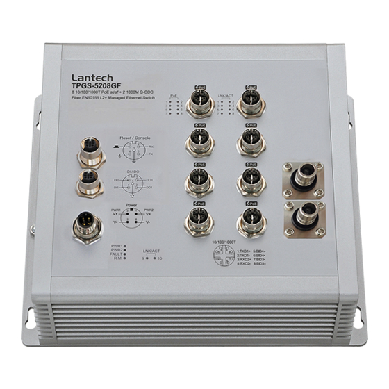
- Page 9 Port description of T(P)GS-5208GF (For TGS-5208GF, there’s no PoE icons and PoE LEDs)
- Page 10 Port description of T(P)GS-5010T (For TGS-5010T, there’s no PoE icons and PoE LEDs)
- Page 11 Port description of T(P)GS-5008T (For TGS-5008T, there’s no PoE icons and PoE LEDs)
-
Page 12: Package Content
2.2 Package Content: Manual CD (by request) Product Console cable... -
Page 13: Ip Protection
2.3 IP Protection The IP Code, Ingress Protection Rating, sometimes also interpreted as International Protection Rating, classifies and rates the degree of protection provided against the intrusion (including body parts such as hands and fingers), dust, accidental contact, and water in mechanical casings and with electrical enclosures. It is published by the International Electrotechnical Commission (IEC) Solid particle protection The first digit indicates the level of protection that the enclosure provides against access... - Page 14 Liquid ingress protection The second digit indicates the level of protection that the enclosure provides against harmful ingress of water. Protected Level Testing for Details against — — protected Dripping Dripping water (vertically Test duration: 10 minutes water falling drops) shall have no Water equivalent to 1 mm harmful effect.
- Page 15 Powerful Water projected in powerful Test duration: at least water jets jets (12.5 mm nozzle) 3 minutes against the enclosure from Water volume: 100 litres per any direction shall have no minute harmful effects. Pressure: 100 kPa at distance of 3 m Immersion Ingress of water in harmful Test duration: 30 minutes...
-
Page 16: Led Indicators
2.4 LED Indicators The diagnostic LEDs that provide real-time information of system and optional status are located on the front panel of the industrial switch. The following table provides the description of the LED status and their meanings for the switch. Color Status Meaning... - Page 17 (5208GF) No device attached...
-
Page 18: Chapter 3 Hardware Installation
Chapter 3 Hardware Installation 1. Unpack switch and check the accessory with packing content list 2. Mount the switch on desired position. For the best ventilation, it is suggested to mount the switch on metallic surface. 3. Connect the M12 connector of power input. Note: Please check the power connector has been connected to the switch correctly before you turn on the power resource. - Page 19 Plug power connector and screw in clockwise direction to fix it. Dual Power Input...
- Page 20 The power input can be supported redundantly. The supply voltage is electrically isolated from the housing. Note: With single power supply of the mains voltage, the device will report a power failure. You can disable this power fail event via web browser.
- Page 21 6. Fitting the device, grounding Install the system in a dry and clean area to protect the switch to get exposed with dirt. Plug the connector to the power supply plug then turn on the power supply. Ground The chassis is grounded via a separate grounding nut (M6). Use toothed locking washers for a good electrical connection.
- Page 22 Ground screw of the switch 7. Connect the M12 connector with RJ-45 data cable, ports are not used shall be caped that comes with the package to insulate the surrounding. Pin assignment of M12 10/100/1000T network connector Make sure the direction of connector is correct before you connect it.
- Page 23 Plug 10/100/1000T connector and screw in clockwise direction to fix it.
- Page 24 8. Connect the Q-ODC connector with Fiber cable, ports are not used shall be caped that comes with the package to insulate the surrounding. Make sure the direction of the connector is correct before you connect it. Plug 1000M connector and move in different directions to make sure the Q-ODC connector is correctly connected with the interface.
- Page 25 Check the status of LED, make sure the switch was in working status. Note: The protection class IP54 is only achieved when bolted together. The other components attaching to the system have to meet with the IP54 protection class in order to reach the whole system IP54 protection. ...
-
Page 26: Chapter 4 Console Management
Chapter 4 Console Management 4.1. Connecting to the Console Port The supplied cable which one end is M12 5-pole connector and the other end is RS-232 connector. Attach the end of RS-232 connector to PC or terminal and the other end of M12 connector to the console port of the switch. - Page 27 The settings of communication parameters Having finished the parameter settings, click ‘OK’. When the blank screen shows up, press Enter key to have the login prompt appears. Key in ‘admin’ (default value) for both User name and Password (use Enter key to switch), then press Enter and the Main Menu of console management appears.
Need help?
Do you have a question about the TGS-5208GF Series and is the answer not in the manual?
Questions and answers