Haier HACI-RP 25 Instructions For Installation, Use And Maintenance Manual
Erp 2018
Hide thumbs
Also See for HACI-RP 25:

Subscribe to Our Youtube Channel
Related Manuals for Haier HACI-RP 25


Summary of Contents for Haier HACI-RP 25
- Page 1 UNITÀ DI RECUPERO CALORE HEAT RECOVERY UNITS HACI-RP 25-130 ErP 2018 MANUALE DI INSTALLAZIONE, USO E MANUTENZIONE INSTALLATION, USE AND MAINTENANCE MANUAL...
-
Page 2: Table Of Contents
IMPORTANTE important PRIMA DI COMPIERE QUALUNQUE OPERAZIONE before performing any operation of the RIGUARDANTE LA MACCHINA LEGGERE maChine Carefully read, ATTENTAMENTE, COMPRENDERE E SEGUIRE understand and follow TUTTE LE ISTRUZIONI DEL PRESENTE MANUALE all instruCtions listed in this manual INDICE: INDEX: 1 - SIMBOLOGIA UTILIZZATA pag. 3 1 - SYMBOL USED pag. 3 2 - AVVERTENZE E REGOLE GENERALI pag. -
Page 3: Simbologia Utilizzata
1 - SIMBOLOGIA UTILIZZATA 1 - SYMBOLS USED La macchina è stata progettata e costruita in accordo alle norme vigenti ed The machine has been designed and constructed according to the current è quindi dotata di sistemi di prevenzione e protezione per i rischi di natura norms and consequently with mechanical and electrical safety devices meccanica ed elettrica che possono riguardare l’operatore o l’utilizzatore. - Page 4 Ricordiamo che l'utilizzo di prodotti che impiegano energia elettrica ed acqua, comporta We remind you that the use of products that employ electrical energy and l'osservanza di alcune regole fondamentali di sicurezza quali: water requires that a number of essential safety rules be followed, including: This appliance must not be used be children and unaided dis- È...
-
Page 5: Caratteristiche Tecniche
CARATTERISTICHE TECNICHE 4 - TECHNICAL FEATURES Recuperatore di calore entalpico statico con efficienza termica • Air-to-air enthalpy heat recovery device, thermal efficiency • fino al 76 % up to 76% • Struttura autoportante in lamiera zincata coibentata internamente • Galvanized steel self-supporting panels, internally and externally ed esternamente;... -
Page 6: Dati Tecnici Unità
5 - DATI TECNICI UNITÀ 5 - UNIT TECHNICAL DATA MODELLO / MODEL HACI-RP m 3 /h Portata aria nominale / Nominal air flow 1000 1300 Pressione statica utile nominale / Nominal external static pressure V/ph/Hz Alimentazione elettrica / Electrical power supply 230 / 1 / 50 - 60 Corrente assorbita massima totale / Total full load amperage... -
Page 7: Dimensioni E Pesi Macchina
6 - DIMENSIONI E PESI MACCHINA 6 - DIMENSION AND WEIGHTS MACHINE Aria espulsa / Exhaust air Aria di rinnovo / Fresh air Peso netto / lordo Dimensioni imballo Dimensione / Dimension [mm] Modello Weight net / gross Packing dimen- Model [Kg] sions [mm]... -
Page 8: Controlli Prima Della Spedizione
7 - CONTROLLI PRIMA DELLA SPEDIZIONE 7 - CHECKS BEFORE SHIPMENT Tutte le unità, prima di essere spedite, sono sottoposte ad una serie di All the units, before being sent, undergo a series of checks, as listed controlli di seguito elencati. below. -
Page 9: Installazione E Messa In Servizio
10 - INSTALLAZIONE E MESSA IN SERVIZIO 10 - INSTALLATION AND START UP 10.1 Definitions 10.1 Definizioni CUSTOMER - The customer is the person, the agency or the company UTENTE - L'utente è la persona, l'ente o la società, che ha acquistato o affittato la macchina e che intende usarla per gli scopi concepiti. - Page 10 10.3 Informazioni preliminari 10.3 Preliminary information • Operare rispettando le norme di sicurezza in vigore, accertandosi della suf- • Work while meeting the current safety regulations, ensuring sufficient ficiente libertà di movimento e della pulizia degli ambienti di installazione space to move and the cleanliness of jobsite •...
- Page 11 10.5 Considerazioni sull’istallazione 10.5 Installation Considerations Condotto di aria fresca Fresh air duct Condotto esterno dell’ aria di rinnovo Barra di sospensione Outside Fresh air duct Suspending Pole Condotto aria di ripresa Aria di espulsione Return Duct Exhaust Duct Out Entrata aria rinnovo Fresh Air in Aria di ripresa...
-
Page 12: Collegamenti Elettrici
1. Assicurarsi che l'altezza del soffitto non sia inferiore alle figure nella 1. Be sure the ceiling height is no less than the Figures in above table B colonna B della tabella. column. 2. L'apparecchio non deve essere installato vicino ai fumi della caldaia. 2. - Page 13 Isolate power during extended off periods. Isolate power and Isolate power during extended off periods. Isolate power and take care when cleaning unit. (Risk of electric shock) take care when cleaning unit. (Risk of electric shock) Clean the filter regularly. A blocked filter may result in poor Clean the filter regularly.
-
Page 14: Messa In Servizio
11.2 Scheda Elettronica di Controllo e Potenza 11.2 Main Board PCB 12 - MESSA IN SERVIZIO 12 - COMMISSIONING Verificare che tutte le dimensioni del cavo, gli interruttori e i collega- Check that all cable sizes, circuit breakers and wire connections are menti a filo siano corretti prima di seguire le seguenti fasi di messa correct before following below commissioning steps: in servizio:... -
Page 15: Pannello Di Comando
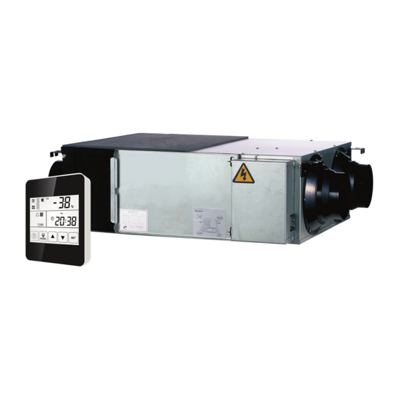
13 - PANNELLO DI COMANDO 13- TOUCH SCREEN Pannello di Controllo Control Panel The controller is surface mounted and comes with a touch screen LCD dis- Il controllore dispone di una interfaccia LCD di tipo “touch screen” fornito play screen, available in option (PTS). come accessorio (PTS). - Page 16 2. Mode switch: 2. Tasto Mode: premere il tasto per selezionare l'opzione RA, OA, FR (EA), SA, press button to choose display the RA, OA, FR (EA), SA setting, MODE MODE impostazione controllo CO2 o controllo umidità. CO2 status or Humidity control status. Impostazioni Temperatura Concentrazione CO2 SA Temperature Setting...
- Page 17 By-Pass OFF By-Pass ON 6. Allarme filtro: 6. Filter alarm: Il pressostato filtro, è installato sulla porta di accesso per monitorare il fil- Pressure switch alarm, the switch is installed on the access door to moni- tro F9; una volta che la differenza di pressione è più grande del valore di tor the F9 filter, once the pressure difference is larger than the setting impostazione, l'interruttore trasmetterà...
- Page 18 Descrizione / Contents Range Default Unit Record Position Funzione di riavvio automatico / Power to auto restart Main control Riscaldatore elettrico disponibile / Electrical heater available Main control Temperatura di apertura by-pass X 5-30 °C Main control By pass opening temperature X Temperatura di apertura by-pass Y 2-15 °C...
- Page 19 DC MAN I 05 000 MCH 00_I 21/03/2018 17.36 Pagina 21 Model / Modello Codice ERV / ERV Code 8. Impostazione del tempo 8. Time setting Tenere premuto il tasto per sei secondi per entrare in modalità di set- Keep pressing the button for 6 seconds, after buzzing to enter the taggio di impostazione del tempo.
- Page 20 B. Impostazione giorno: sotto l'interfaccia di impostazione giorno, preme- B. Day setting: under day setting interface, press button for short to re il tasto brevemente per iniziare l'impostazione giorno, premendo i begin the day setting, by pressing UP and DOWN buttons to select the pulsanti su e giù...
- Page 21 D. Impostazione timer settimanale OFF: nel menù timer settimanale D. Weekly timer off setting: under weekly timer off setting interface, press OFF, premere il tasto di volta in volta per selezionare periodo di lune- button for short to begin the timer off setting, press button time dì...
- Page 22 15 - TABELLA DI INDIRIZZO ModBus 15- TABLE of ModBus ADDRESS Indirizzo Contenuto Gamma Predefinita Posizione Record ModBus Non usato Controllo principale Non usato Controllo principale By-pass temperatura di apertura X 5-30 19 °C Controllo principale Bypass intervallo temperatura di apertu- 2-15 3 °C Controllo principale...
- Page 23 15 - TABELLA di INDIRIZZO ModBus 15- TABLE of ModBus ADDRESS ModBus Address Content Range Default Record Position Useless Main Control Useless Main Control By-pass opening temperature X 5-30 19 °C Main Control By-pass opening temperature range Y 2-15 3 °C Main Control Defrosting interval 15-99...
- Page 24 16 - INTRODUZIONE DEL SELETTORE 16 - INTRODUCTION OF DIAL SWITCH Selettore di configurazione funzionalità Dial switch 1. SW 4-1: OFF - Sbrinamento tramite ventilatore di espulsione EA 1.SW 4-1: OFF - Traditional EA expulsion fan defrost ON - OA side electrical heater defrost ON - Sbrinamento con resistenza elettrica lato OA 2.SW 4-2: OFF - Auto by pass 2.
- Page 25 17 - INSTALLAZIONE ACCESSORI 17 - ACCESSORIES INSTALLATION PRIMA DI INTRAPRENDERE QUALSIASI OPERAZIONE DI INSTALLA- BEFORE UNDERTAKING WHICHEVER INSTALLATION OPERATION ZIONE ASSICURARSI CHE LA MACCHINA SIA SPENTA E CHE NON MAKE SURE THAT THE MACHINE IS SWITCH OFF AND THAT IT CAN POSSA ESSERE ACCIDENTALMENTE COLLEGATA ALLA CORREN- NOT BE ACCIDENTALLY CONNECTED TO THE POWER.
- Page 26 Sensore umidità - USW Humidity sensor - USW Il Sensore di umidità è fornito completo di cavo lungo 5 metri e con- The humidity sensor comes complete with a 5 metre long cable and nettori per il collegamento alla scheda elettronica a bordo macchina. connectors for connection to the electronic board on the machine.
- Page 27 18- MANUTENZIONE 18 - MAINTENANCE PRIMA DI INTRAPRENDERE QUALSIASI OPERAZIONE DI MANUTEN- BEFORE UNDERTAKING WHICHEVER MAINTENANCE OPERATION ZIONE ASSICURARSI CHE LA MACCHINA SIA SPENTA E CHE NON MAKE SURE THAT THE MACHINE IS SWITCH OFF AND THAT IT CAN POSSA ESSERE ACCIDENTALMENTE COLLEGATA ALLA CORREN- NOT BE ACCIDENTALLY CONNECTED TO THE POWER.
- Page 28 CADENZA OPERAZIONE / OPERATION TIMING Parte Fissa Fixed Part Porta Pannello Ispezione Service Pannel APERTURE ISPEZIONE SERVICE OPENING Rimuovere le due viti per sbloccare il pannello correttamente. Release the 2 screws of the ispection panel with the proper handle. ESTRAZIONE FILTRI FILTERS EXTRACTION Rimuovere i due filtri facendoli scorrere.
- Page 29 19 - LOCALIZZAZIONE DEI GUASTI 19- BREAKDOWN DIAGNOSTIC In caso di problematiche, l'utente può tentare di risolvere l’anomalia. User can use the unit after trial operation. Before contacting us, you can Prima di contattare l’azienda fornitrice, seguire le indicazioni della tabella make self trouble shooting following below chart in case of any failure.
- Page 30 20 - PARTI DI RICAMBIO 20 - SPARE PARTS pag. 32 Manuale di Installazione Uso e Manutenzione - Installation, Use and Maintenance Manual...
- Page 31 Serie di ricambio / Spare parts Modello / Model Nome Parti / Parts name Codice / Code Quantità / Qty ERV Flangia circolare di raccordo canale / Spigot MV00BOC0MICH0250 Recuperatore di calore / Plate heat exchanger PR000E000MICH025 Motore / Motor (50 Hz/60Hz) MTE00000MICH0250 Girante / Impeller VT000GIRMICH0250...
Need help?
Do you have a question about the HACI-RP 25 and is the answer not in the manual?
Questions and answers