Advertisement
Quick Links
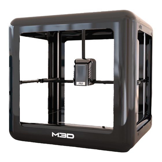
Extruder Gear Replacement Guide for the M3D PRO
In this guide we will explain how to replace the extruder gear for your M3D PRO. You will need
a 2.0mm/1.5mm hex screwdriver for the disassembly and you'll want to be in a antistatic
environment. Some electronics will be exposed during the disassembly and there is a chance
you could damage them. We recommend not working on a carpeted area and to discharge
before working. You can do this by touching something metal (Not the printer) for at least one
second. Wearing an antistatic wrist-wrap would be good. Link for a wrist-wrap here
https://www.amazon.com/Rosewill-Anti-Static-Components-RTK-002-
Yellow/dp/B004N8ZQKY/ref=sr_1_1?ie=UTF8&qid=1494531998&sr=8-1-
spons&keywords=anti+static+wrist+strap&psc=1
Although, it is highly recommended to use an antistatic wrist-wrap, if you do not have access
to the antistatic wrist-wrap, you can do the repair process by having a metal contact to your
body throughout the repair.
Since the M3D PRO 3D printer is highly static device as there are various PCBs involved, if the
repair process is carried out without following the above recommendation and the customer
end up frying the electronics, they would need to send back their printers to M3D headquarters
for replacement.
Step 1.
The first step will be to remove the front cover from the Pro. To do this you will need
to remove the hex screws from the cover. There are a total of 8 screws in each cover. Four
screws on the top and four screws on the bottom.
1.
Advertisement

Related Manuals for m3d PRO


Summary of Contents for m3d PRO
- Page 1 Extruder Gear Replacement Guide for the M3D PRO In this guide we will explain how to replace the extruder gear for your M3D PRO. You will need a 2.0mm/1.5mm hex screwdriver for the disassembly and you’ll want to be in a antistatic environment.
- Page 2 Once you have removed all of the screws you can gently start pulling the cover off the Pro. Try pulling out the top a little first and then move onto the bottom. Keep going back and forth from top to bottom until the cover is removed.
- Page 3 Step 3. Once the front cover has been removed move onto the rear cover. The process will be similar to the front cover. The only difference will be that there is a grommet attached to the cable assembly on the bottom that may need to be removed to remove the rear cover.
- Page 6 Step 4. Once the front and back covers are removed you will be left with the box top rails. These can easily be removed by just lifting them up and off the rods.
- Page 7 Once the rails are removed be sure to check the rods to make sure all the spring washers are there. You should have one spring washer on each rod. You may want to remove these and keep them in a safe place so you do not lose them. Step 5.
- Page 8 M1012 and hit enter then type G33 and hit enter you can now raise the gantry all the way to the top until you will be able to remove the extruder without issue. Once free Disconnect The Pro from the USB and Power...
- Page 9 X rods. If you have one of our early Pro’s then the rods might have been press fitted on. To remove these you will need to twist the gantry’s back and forth to loosen the fit and remove the rods.
- Page 11 Step 8. If you are running into any grinding noises please continue with this step. Once the extruder is off you should be able to see the X gear and encoder wheel inside the holes where the X rods are inserted. A encoder wheel rubbing up against the encoder could be causing your noise issue.
- Page 12 Step 10. Once the front cover is off you will need to unplug the fan cable. The fan cable is located at the top of the “X Board” located on the right side of the extruder motor.
- Page 13 Step 11: Now you would need to take the internal print head assembly out that consists of the cable assembly, extruder housing and the X housing as shown in the picture below as well as remove the clear wallE cover:...
- Page 14 Step 12: Next, disengage the cable assembly from the extruder housing but taking off the screw that sits on the top of the small sheet metal as shown in the picture below: Step 13: Remove the two screws that joins the extruder housing to the X housing as shown in the picture below:...
- Page 15 Step 14: Remove the nozzle subassembly in order to get access to screw that is hidden behind the black teflon tube (teflon short) as shown in the picture below:...
- Page 16 Step 15: Remove the screw that holds the extruder encoder to loosen it as shown in the picture below: Step 16: The next step would be take the extruder motor out so that the old extruder gear can be pulled out for replacement. The extruder motor is removed and placed seperate as shown in the three picture below:...
- Page 18 Step 17: Now the extruder gear needs to pushed out of the extruder housing as shown in the picture below:...
- Page 19 The extruder gear after being pushed out will look like as shown in the picture below. The extruder gear has a small bearing that sits on the top and it remained inside the extruder housing when the old extruder gear was pushed out and thus is not shown in the picture below.
- Page 20 Step 19: After placing the extruder gear as shown in the above picture, use the back of the screw driver to push the new extruder gear deep into the extruder housing such that it is pushed all the way back in as shown in the picture below:...
- Page 21 NOTE: See how the bearing that seats on the top of the extruder gear is pushed all the way back in as shown in the picture above (shown by the red arrow). Step 20: Now engage the extruder housing and the X housing back together as shown in the pictures below:...
- Page 22 Step 21: Lastly, engage the cable assembly through the small sheet metal with its appropriate screw to the extruder housing as shown in the picture:...
- Page 23 This is how the finally subassembly should look like once all the components (extruder housing, X housing and cable assembly are put together):...
Need help?
Do you have a question about the PRO and is the answer not in the manual?
Questions and answers