
Related Manuals for Adleepower AM-60L

Summary of Contents for Adleepower AM-60L
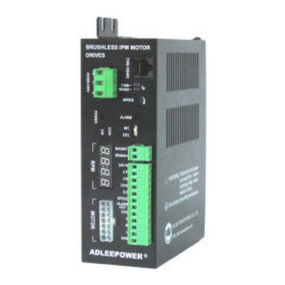
- Page 1 ADLEEPOWER INSTRUCTION MANUAL BRUSHLESS IPM MOTOR & DRIVES THANK YOU VERY MUCH FOR YOUR PURCHASE OF ADLEE PRODUCTS. PLEASE READ THIS INSTRUCTION MANUAL BEFORE INSTALLATION.
-
Page 2: Table Of Contents
CONTENTS 1. PREFACE 2. NAMEPLATE 3. SPECIFICATION 4. DIMENSIONS 5. ENVIRONMENTAL REQUESTS 6. FUNCTION DESCRIPTION 7. OPERATION AND CONNECTION 8. Motor T-N curve 9. APPLICATION 10. TROUBLE SHOOTING 11. REPAIRING AND MAINTENANCE Appendix... -
Page 3: Preface
1. Preface This D305 drive and brushless servomotor made by ADLEE Powertronic., Ltd. Read this instruction manual throughly before operation. This manual will be helpful in the installation, parameter setting and troubleshooting of the BLDC motors and drives. To guarantee safe operation of the equipment, read the following safety guide- lines before connecting power to the drives. - Page 4 Installation CAUTION Impacts and shocks applied to the shaft end will damage the rotary sensor and ball bearings. Pay more attention when drive elements such as pulleys, clutch disks, toothed wheels etc. DANGER Be sure to install the unit on flame-resistant material such as a steel plate.
- Page 5 Do not stop operation by switching of electromagnetic contactors on the primary. CAUTION Tighten terminal screws. CAUTION When using D305 drives should match to ADLEEPOWER ® AM series motors. If using other brand motors can cause the driver or motor dam- age.
- Page 6 Operation CAUTION Danger of getting burnt! The surfaces of motors can ℃ ℉ reach temperatures of up to approx. 100 (212 A touch guard is to be provided where necessary. DANGER Danger of injury from shaft keys being slung out. Motor may only be operated as installed.
-
Page 7: Nameplate
2. Nameplate Motor ADLEEPOWER Model No. Rated power Brushless DC Motor Implied protection Input voltage Output Model AM-180L 180W Volts AC220V Insulation grade Rated current AMP.S 0.55 INS. DRIVE 45°C/113°F D305 Drive model Max. rpm 2000 DATE Ambinent Temp ADLEE POWERTRONIC CO., LTD. -
Page 8: Specification
3. Specification AM-60 AM-90 AM-120 AM-180 AM-250 AM-370 Model No. L/M/H L/M/H L/M/H L/M/H L/M/H Input Voltage 100~130VAC / 1ψ OR 200~230VAC / 1ψ (TN system) Input Frequency 50 / 60 Input Rated Current Max. Input Current (For 220V input) Max. - Page 9 AM-60 AM-90 AM-120 AM-180 AM-250 AM-370 Model No. L/M/H L/M/H L/M/H L/M/H L/M/H Load ± 1% Below (0~Rated Torque at rated speed) Speed Voltage ± 1% Below (Source voltage± 10% at rated speed No Load) regulation Temperature ± 1% Below (0~40℃ / 32~104℉ at rated speed No Load) Motor Insulation/ ※...
-
Page 10: Dimensions
4. Dimensions 4-1 Motor dimensions Unit : mm Lead cable length : 1M (3.28ft) Output Shaft End □ ∮ ∮ ∮ LA LB B1 B2 ∮ ED Q E 20 25 28 99.5 127.5 160.5 12 13.5 4 114.5 146.5 179.5 104 8.5 83 2.5 8 61 33 109.8 28.5... - Page 11 4-2 Drive dimensions Unit : mm...
- Page 12 4-3 F306 dimensions Unit : mm...
-
Page 13: Environmental Requests
5. Environmental requests Operation ℃ ℉ Air temperature -10~45 (14~113 Air pressure 86~106kPa Attitude Under 1000 meters Less than 20HZ : maximum 9.86m/s Vibration 20~50HZ : maximum 5.88m/s Storage ℃ ℉ Air temperature -20~60 (-4~140 Air pressure 86~106kPa Humidity Less than 90%, no frosting Transportation ℃... - Page 14 Motors Drives...
-
Page 15: Function Description
6. Function Description 6-1 Digital operation panel CHARGE F306 REMOTE CONTROL FUNC STOP Keypad Function Description Forward Commands forward run Reverse Commands reverse run Cursor Select the digit movement Down Decrease the parameter value 9~0 Increase the parameter value 0~9 Memory Saves the setting parameter value storage... - Page 16 6-2 Terminals...
- Page 17 6-3 Main circuit terminals Wire Wire type Torque 14AWG~16AWG Standard copper only 8Kg-cm Input(L1,L2, ℃ (2.0mm ~1.3mm (300V/80 ) (6.95lb-in) External control 24AWG Standard copper only 5Kg-cm ℃ signal terminals (0.2mm (300V/80 ) (4.34lb-in) 14AWG~16AWG Standard copper only 8Kg-cm FG screw (M4) ℃...
- Page 18 6-4 Terminal description Input source power line added 20A line fuse (or equivalent) is recommanded for safety. Do not try to modify the wire between motors and drives. The extension cable is available from factory. Do not connect the shielding wires to any other component. Make sure all plugs are tight enough with socket.
- Page 19 █ Speed : 1. Close loop control mode (Default) Motor stops operation if speed command is lower than minimum speed. L series : 150~2000 RPM M series : 150~3000 RPM H series : 300~6000 RPM HX1 series : 130~5000RPM HX2 series : 300~9999RPM Default value : 0RPM 2.
- Page 20 █ 2. CF : Analog command mode (CD19=0) ● OFF : Panel VR ON : Terminal control (HML) Digital command mode (CD19=1) ● Close loop control OFF : CD28 speed setting ON : CD29 speed setting Open loop control OFF : CD34 speed setting ON : CD35 speed setting (Note : F306 does not relate to CF setting.) █...
- Page 21 6-5 RS485 connector 8765 4321 Color Black Red Orange Yellow Green Blue Purple Brown Symbol GND VCC RFA0 Connect to F306 or RS485 ※ This connector is for both F306 and RS485. Set JP jumper for selection. 6-6 F306 panel display Display shows command speed initially.
- Page 22 6-8 Grounding 1. Be sure ground both the inverter and motor. 2. Keep grounded leads as short as possible. 3. Shield cables used to protect low-level signal leads should grounded at one end point. Ω 4. Provide class 3 grounding (0.1 or less) for a terminal.
-
Page 23: Operation And Connection
7. Operation and connection 7-1. Parameter list Display Adjust Function Default Value Unit Remark code Range CD00 Parameter lock 0~9999 0 : 2000RPM(L) 1 : 3000RPM(M) CD01 Model setting As model 2 : 6000RPM(H) 3 : 5000RPM(HX1) 4 : 9999RPM(HX2) Command 0 : Open loop control CD02... - Page 24 Display Adjust Function Default Value Unit Remark code Range CD14 Reserved CD15 Display ratio 1~200 Acceleration 0 : Linear CD16 mode 1 : S curve CD17 Current limit 20~300 0 : CW and CCW CD18 Direction limit 1 : CW only 2 : CCW only Analog/digital CD19...
- Page 25 Display Adjust Function Default Value Unit Remark code Range L : 150~2000RPM M : 150~3000RPM speed in CD29 2000 0~9999 H : 300~6000RPM digital HX1 : 130~5000RPM HX2 : 300~9999RPM CD30 Reset to default 0 or 1 0 : SLOW DOWN ACC./DEC.
- Page 26 Communication address description Display Adjust Function Default Value Unit Remark code Range RS485 speed command 0 : Stop or reset RS485 1 : CW operating 2 : CCW command 3 : Stop Motor speed (RPM) Motor running condition Error code Note : 1.
- Page 27 7-2 F306 parameter setting sequence A. In standby condition, press to be in setting mode. Press FUNC if it is not in standby mode. STOP B. Press to the parameter number. Press return to standby mode if there is no need to change value. C.
- Page 28 7-3 Command source setting Terminal, RS485 and remote control (F306) are the command source for selection. Use JP jumper to select it. A. Remote control (F306) a. Analog/digital speed input a-1. CD19=0 analog input Speed is controlled by F306 VR. a-2.
- Page 29 D. Terminal control 1. Put two jumpers on JP. 2. Set control power in INT position if using internal power. 3. Two speeds control : CD19=0, 1 speed is speed VR on panel, 2 speed is HML on terminal. CD19=1, 1 speed is CD28 value, 2 speed speed is CD29 value.
- Page 30 7-4. Signal input circuit INT. I/O external/internal power supply select Photocoupler INPUT EXT. SLOW DOWN INPUT ■ EXT voltage is 24VDC ± ■ Using internal power supply control Set I/O external/internal power supply select at INT. motor cannot operate if I/O external/internal power supply select is at EXT.
- Page 31 <Contact control> Controller D305 Drivers Relay INPUT ■ Using external power supply control Controller D305 Drivers Set I/O external/ internal power INPUT DC24V supply select at EXT. Transistor INPUT...
- Page 32 ■ Note : controller with built-in clamp diode Controller D305 Drives INT. EXT. INPUT Compatible with TLP521 Clamp diode Ω +24V INPUT Transistor It is necessary to set I/O external/internal power supply select at EXT, when controller with built-in clamp doide has been used. If I/ O external/internal power supply select is not correct, then motors will run at controller power ON/OFF.
- Page 33 7-5. Example of application of signal output circuit> Controller D305 Drives Current limit DC24V resistor 2.7K Ω SPEED Photocoupler [Speed out] H, HX2 series : 6 pulses/per turn L, M, HX1 series : 12 pulses/per turn Motor speed can be measured from the frequencies of terminal “SPEED OUT”.
- Page 34 7-4 Parameter description Parameter lock Setting Range 0 ~ 9999 Default value CD00 0 : Lock. 1 : Unlock. Model setting Setting Range 0 ~ 4 Default value As model CD01 0 : 2000RPM(L). 1 : 3000RPM(M). 2 : 6000RPM(H). 3 : 5000RPM(HX1).
- Page 35 Brake mode Setting Range 0 ~ 12 Default value CD03 CD03 value Operation mode SLOW DOWN terminal 0 , 10 ACC. time start with fast stop 0 , 10 ACC. time start with DEC. time stop 1 , 11 ACC. time start with DEC. time stop ON / OFF 2 , 12 ACC.
- Page 36 Maximum speed Setting Range 130 ~ 9999 limit 2000(L) / 3000(M) / Default value 6000(H) / 5000(HX1) CD04 / 9999(HX2) Ex. CD04=2500 L : set under 2000RPM M : set under 3000RPM 3000 H : set under 6000RPM HX1 : set under 5000RPM 2500 HX2 : set under 9999RPM Note : This parameter does not...
- Page 37 Speed command Setting Range 1000 ~ 9999 RPM / 5V 2000(L) / 3000(M) / Default value 6000(H) / 5000(HX1) CD06 / 9999(HX2) The reference speed command at 5V in close loop. Note : This parameter does not work in open loop control. Speed command 0~500 : 0~500RPM Setting Range...
- Page 38 Deceleration time Setting Range 0.2 ~ 600.0 Default value CD09 The deceleration time 1 rate speed to 0 RPM. S curve Setting Range 0.2 ~ 15SEC Default value 0.2SEC CD10 When CD16=1, Acceleration time = CD08+CD10 Deceleration time = CD09+CD10 Note : CD10 content must be smaller than CD08 or CD09 content .
- Page 39 Display ratio Setting Range 1 ~ 200 Default value CD15 Display speed = (set or real speed) / CD15 This functiion is good for motor with gearbox. The display can show the gearbox output speed. S curve Setting Range 0 ~ 1 Default value CD16 0 : Liner.
- Page 40 Direction limit Setting Range 0 ~ 2 Default value CD18 0 : CW and CCW. 1 : CW only. 2 : CCW only. Analog / digital speed input Setting Range 0 ~ 1 Default value CD19 0 : Analog command is from pannel or terminal VR or F306 VR. 1 : Digital command is from CD28 or CD29 setting.
- Page 41 Address setting Setting Range 1 ~ 255 Default value CD21 Each drive must have unique identified address if they are con- trolled by RS-485 communication. Each address cannot be dupli- cated. Transmission speed Setting Range 0 ~ 3 Default value CD22 Setting the transmission speed between computer and drive.
- Page 42 Communicator Setting Range 0 ~ 7 protocol Default value CD24 A. Data format 0 : 8,N,1 RTU (1 start bit+8 data bits+1 stop bit) 8,N,1 RTU(10bits)(character frame in hexadecimal) Start bit 0 1 2 3 4 5 6 7 Stop bit 1 : 8,N,2 RTU (1 start bit+8 data bits+2 stop bit) 8,N,2 RTU(11bits)(character frame in hexadecimal) Start bit 0 1 2 3 4 5 6 7 Stop bit...
- Page 43 6 : 8,E,1 ASCII (1 start bit+8 data bits+1 Even bit+1 stop bit) 8,E,1 ASCII(11bits)(character frame in hexadecimal) Even Start bit 0 1 2 3 4 5 6 7 Stop bit parity 7 : 8,O,1 ASCII (1 start bit+8 data bits+1 Odd bit+1 stop bit) 8,O,1 ASCII(11bits)(character frame in hexadecimal) Start bit 0 1 2 3 4 5 6 7 Stop bit...
- Page 44 2. ASCII Start character=' : ' (3AH) Communication address : Address Hi 8-bit address consists of 2 ASCII Address Lo codes. Command code : Function Hi 8-bit command consists of 2 ASCII Function Lo codes. Data (n-1) Contents of data : n*8-bit data consist of 2n ASCII codes.
- Page 45 (1) 03H : Read drive's setting Computer command message D1 : Communication address (00~FFh) D2 : Function code (03h) D3 : Parameter number (H) (00h) D4 : Parameter number (L) (0~3Dh) D5 : Quantity of parameter (H) (word count) (00h) D6 : Quantity of parameter (L) (word count) (00~10h) D7 : CRCL or LRC (H)
- Page 46 2. ASCII Computer command message Drive response message Address '3' Address '3' Address '4' Address '4' Function '0' Function '0' Function '3' Function '3' # of data '0' D3 Start address '0' count by byte '4' Start address '0' Start address '1' Start address 'C' D4 CD28 content '0' CD28 content '3'...
- Page 47 Note 1 : The parameter values can be in integer, decimal and negative. Each value has different process to read and write. Refer to 7-1 lists to find out the minimum unit and value range for each parameter. ≧ a. In computer command message D5 80, this value is negative.
- Page 48 (2) 06H : Write parameter setting into drive Computer command message D1 : Communication address (00~FFh) D2 : Function code (06h) D3 : Parameter number (H) (00h) D4 : Parameter number (L) (0~1Fh) D5 : Content of data (H) (0~FFh) D6 : Content of data (L) (0~FFh) D7 : CRCL or LRC (H)
- Page 49 Ex. Write parameter setting CD04=1500RPM into address 52(34H) driver. 1. RTU Computer command message : CRCL CRCH Drive response message : CRCL CRCH 2. ASCII Computer command message Drive response message Address '3' Address '3' Address '4' Address '4' Function '0' Function '0' Function '6' Function '6'...
- Page 50 Ex. Computer commands the address 52(34H) driver to operate CW at 1500RPM. 1. RTU Step 1 : write address 28(1CH)=1500RPM Computer command message : CRCL CRCH Drive response message : CRCL CRCH Note : Process step 2 directly if address 28 is set in 1500RPM already.
- Page 51 2. ASCII Step 1 : write address 28(1CH)=1500RPM Computer command message Drive response message Address '3' Address '3' Address '4' Address '4' Function '0' Function '0' Function '6' Function '6' D3 Number of parameter '0' D3 Number of parameter '0' Number of parameter '0' Number of parameter '0' Number of parameter '1'...
- Page 52 Step 2 : write address 100(64H)=1 Computer command message Inverter response message Address '3' Address '3' Address '4' Address '4' Function '0' Function '0' Function '6' Function '6' D3 Content of data '0' D3 Content of data '0' Content of data '0' Content of data '0' Content of data '6' Content of data '6'...
- Page 53 (3) 08H : Communication loop detection Computer command message D1 : Communication address (0~FFh) D2 : Function code (08h) D3 : Data 1 (0~FFh) D4 : Data 2 (0~FFh) D5 : Data 3 (0~FFh) D6 : Data 4 (0~FFh) D7 : CRCL or LRC (H) (0~FFh) D8 : CRCH or LRC (L) (0~FFh)
- Page 54 2. ASCII Computer command message Drive response message Address '3' Address '3' Address '4' Address '4' Function '0' Function '0' Function '8' Function '8' D3 Content1 '1' D3 Content1 '1' Content1 '1' Content1 '1' Content2 '2' Content2 '2' Content2 '2' Content2 '2' D5 Content3 '3' D5 Content3 '3'...
- Page 55 CRC(Cyclical Redundancy Check) is calculated by the following steps: Step 1. Load a 16-bit register (called CRC register) with FFFFH. Step 2. Exclusive OR the first 8-bit byte of the command mes- sage with the low order byte of the 16-bit CRC register, putting the result in the CRC register.
- Page 56 E. Communication error drive respond Once communication error happend, drive will respond “Function code and 80H” and communication error code to master system. Communication error code definition Error code Description Function code error only (03/06/08 available) Illegal data value(data value is outside limit value) Illegal data address(data address is not available) Illegal command, drive can't do this command Check sum error...
- Page 57 EX. In drive 01 write 1B58(7000rpm) to parameter address 04, but CD04 upper limit is 6000rpm (1770H). 1.RTU Computer command message : CRCL CRCH Drive response message : CRCL(C3H) CRCH(A1H) 2.ASCII Computer command message Drive response message Address '0' Address '0' Address '1' Address '1' Function '0'...
- Page 58 Communication loss time Setting Range 0.1 ~ 100.0SEC Default value 0.5SEC CD25 Set communication loss time. When communication loss time over CD25 setting, BLDC drive will active as CD26 selected. Note : This function does not effect in standby condition. Transmission Setting Range 0 ~ 3...
- Page 59 speed in Setting Range 0 ~ 9999RPM digital Default value 1000RPM CD28 L : 150~2000RPM M : 150~3000RPM H : 300~6000RPM HX1 : 130~5000RPM HX2 : 300~9999RPM Note : This parameter does not work in open loop control. For RS485 speed command address. speed in Setting Range 0 ~ 9999RPM...
- Page 60 2nd ACC./DEC. time terminal setting Setting Range 0 ~ 1 Default value CD31 0 : Slow down refer to CD03 stop mode. 1 : 2nd Accel. and Decel. time select S_D terminal “OFF“ select CD08 and CD09. S_D terminal “ON“ select CD32 and CD33. ON means S_D and EXG are short.
- Page 61 2nd open loop digital speed Setting Range 0 ~ 1000 command Default value CD35 When CD02=0, CD19=1 CF “OFF“ open loop digital speed command input by CD34. CF “ON“ open loop digital speed command input by CD35. Note : CD34 or CD35 setting 1000 mean 100% duty, 100 mean 10% duty.
- Page 62 Clear errors record CD40 Set CD40=1 to reset CD36~CD39 records. Errors record flow-chart when Error occur. The new content will shift the other contents to one higher CD code and the highest one will be dropped. Error occur CD37 CD36 CD38 CD39 Loss...
- Page 63 Communication address description RS485 speed command 28(1CH),29(1DH) ,34(22H),35(23H) Close loop speed command : Setting range is 0 ~ 9999. CF “OFF“, CD28(1CH) content. CF “ON“, CD29(1DH) content. Open loop speed command : Setting range is 0 ~ 1000. CF “OFF“, CD34(22H) content. CF “ON“, CD35(23H) content.
- Page 64 Motor running codition 102(66H) This real motor running condition. 1 : CW 2 : CCW 3 : STOP Error code 103(67H) Use RS485 protocol 03H to read error code if driver is in protec- tion mode. 2 : Motor overheat. 3 : Driver over current / over heat / over voltage.
-
Page 65: Motor T-N Curve
8. Motor T-N curve Torque Max. torque Limited duty region Rated torque Continue duty region Min. speed Rated speed... -
Page 66: Application
9. APPLICATION CD03=0 : Immediately stop, provide little brake force at standby mode. Drivers will continue to provide little brake force at standby mode , motor does not free CD03=10 : Immediately stop, does not provide little brake force at standby mode. -
Page 67: Trouble Shooting
10. Trouble shooting Motors free run to stop when protect functions are effected. Disconnect power to reset the protect function. For safety , make sure all problems are solved before reconnect power. To wait more than 5 minutes to reconnect power after disconnect power. - Page 68 Display Description Check point and suggestion symbol OPE1 Parameter lock CD00 set 1. Motor direction limiter. OPE2 FWD or REV only See function description CD18. Source of speed Set at analog command, but use F306 keypad to OPE3 command error change speed.
-
Page 69: Repairing And Maintenance
5. Do NOT use water, solvent or volatilizable liquor to clean driver. Please use dry clothes to clean stain or use compressed air to clean dirt. 6. Please call us or send drives to ADLEEPOWER ® when you can’ t obviate problems. - Page 70 Maintenance Period : Daily Check items Methods and criteria Confirm the ambient temperature, vibration, humidity and see if there Visual inspection and is any oil, gas, dust or water measurement with equipment Ambient conditions drops. around the drive Confirm if there are any dangerous Visual inspection objects around.
- Page 71 Maintenance Period : Half Years Check items Methods and criteria Confirm if there is any abnormal sound , vibration, deformation or Visual and aural inspection damage. Confirm if there are any loose Mechanical parts Tighten the screws screws. Confirm if there is any color change by overheating, dust or Visual inspection dirt.
-
Page 72: Appendix
Appendix 1. F306 remote operator extension cable A-0000-F306G3 F306 Remote operator E-092A-010200 1 meter extension cable E-092A-030200 3 meter extension cable E-092A-050200 5 meter extension cable E-PEAA-8P8C02 Extension connector... - Page 73 INSTRUCTION MANUAL PART NO : E-PHAA-EAMA02 Model : series MAY. 2018 7 edition ADLEEPOWER SERVICE OFFICE Taiwan Wu Han (China) Tel No : 886-4-25622651 Tel No : 86-27-88872826 Fax No : 886-4-25628289 Fax No : 86-27-88603986 E-mail : webmaster@adlee.com URL : http://www.adlee.com...
Need help?
Do you have a question about the AM-60L and is the answer not in the manual?
Questions and answers