
Related Manuals for Tecnoalarm Tecnofire TFA2-596

Summary of Contents for Tecnoalarm Tecnofire TFA2-596
- Page 1 TFA2-596 - TFA4-1192 Addressable fi re alarm systems Installation Release: FW release: 2.0.00 Models: TFA2-596 - TFA4-1192 Programming SW release: Update: 07/2019 Language: English...
- Page 2 TFA2-596 - TFA4-1192...
- Page 3 INDEX The manufacturer, Tecnoalarm S.r.l., declares that the present equipment complies with the Directives LVD 2014/35/EU and EMC 2014/30/EU as well as the regulation CPR 305/2011. The full text of the EU Declaration of Conformity is available at the following internet address: www.tecnofi...
- Page 4 TFA2-596 - TFA4-1192...
- Page 5 INDEX 1 - GENERAL REFERENCES 2 - SYSTEM RESOURCES 3 - SYSTEM SPECIFICATIONS 4 - WARNINGS FOR INSTALLATION Casing Fixing of the casing Connection cables Compliance with EN 60950-1- Electrical Safety Secondary power supply 5 - USER INTERFACE Control panel Access levels and codes Function keys Signaling LED...
- Page 6 9 - ELECTRONIC BOARDS TFA2-596 terminals Terminals TFA4-1192 terminals Terminals CPU board Power supply 10 - CONNECTION 10-1 Detection loop connection 10-2 Siren connection 10-3 RS485 bus connection 10-4 Potentiation of the secondary power supply 10-5 TFA2-596 additional power supply connection 10-6 TFA4-1192 upgrade of the secondary power supply 10-7...
-
Page 7: General References
fi re alarm systems and the specifi c provisions for installation, electrical safety and maintenance. In addition, he must have a thorough knowledge of the products, acquired through specifi c training at Tecnofi re (division of Tecnoalarm S.r.l.). Environmental requirements The control panel and all the system components must be installed inside structures or buildings with climatic characteristics (temperature and non-condensing relative humidity) that comply with the standards applied during certifi... -
Page 8: Periodic Maintenance
Periodic maintenance To guarantee the effi ciency of the fi re alarm system, it is necessary to provide for an appropriate maintenance program. The frequency of maintenance depends on different aspects, however, it is recommended to have the system serviced at least once every 6 months. -
Page 9: System Resources
2 - SYSTEM RESOURCES The TFA2-596 control panel manages 2 and the TFA4-1192 manages 4 detection loops. The number of available detection loops can be increased by connecting other control panels. The maximum network confi guration includes 16 control panels with 4 detection loops. General specifi... - Page 10 TFA2-596 - TFA4-1192...
-
Page 11: System Specifications
3 - SYSTEM SPECIFICATIONS The scope of the TFA2-596 and TFA4-1192 control panels is to build small, medium-sized and large addressable systems for the automatic detection of fi re. The systems can be composed of a network of maximum 16 control panels, permitting, in its maximum network confi... - Page 12 Synoptic repeater The synoptic repeater panel performs the same functions as the repeater and, in addition, it manages dynamically or on request up to 32 fl oor plans with up to 32 interactive icons each. Additional power supply The system provides for the use of additional power supplies, which allow to increase the power supply and autonomy of the system. The power supplies can be freely distributed within the infrastructure of the loop.
- Page 13 TFA2-596 • TFA4-1192 - Technical and functional specifi cations 796 (TFA4-1192) TFT-7 Total connectable detectors 398 (TFA2-596) TFT-7S Serial expansions (max. 16) Telephone Total detectors per loop communicator Expandability 396 (TFA4-1192) Ethernet interface Detectors Total connectable modules Modules 198 (TFA2-596) Network confi...
- Page 14 TFA2-596 - TFA4-1192...
-
Page 15: Warnings For Installation
4 - WARNINGS FOR INSTALLATION 4-1 - Casing ALARM 16/02/2019 Access level 1 08:00:00 RESET PREALARM Fire control panel TECHNICAL ALARM EVACUATE GENERAL FAILURE Version: 2.0.00 ENG PWR SPLY FAILURE Control panel working MONITORED SYSTEM FAILURE BATTERY STOP/RESET Level 2 Level 3 Level 4 SIR. -
Page 16: Connection Cables
4-2 - Fixing of the casing The casing of the control panel must be fi xed in a position that guarantees adequate protection from accidental shocks and at a height that grants full access to the operator. Consider the space necessary for fully opening the casing door (approx. 60cm). Fix the casing horizontally on a solid surface using 4 dowels with 8mm diameter. - Page 17 4-4 - Compliance with EN 60950-1- Electrical Safety Ground connection The ground connection must comply with the valid European standards. It is mandatory to connect the ground conductor between the casing and the door. External circuit breaker The power supply of the control panel is not equipped with a circuit breaker. To guarantee accordance of the installation with the valid European standards, it is necessary to connect an external circuit breaker or a bipolar mains switch (16A curve C, opening stroke min.
-
Page 18: Secondary Power Supply
4-5 - Secondary power supply Battery information 49 50 51 52 The batteries must always be two. Never use batteries of different BUS MASTER manufacturers and capacities. Capacities lower than 12Ah, 0 21 22 23 24 25 26 27 28 29 30 31 32 33 34 35 36 37 38 39 40 41 42 43... -
Page 19: User Interface
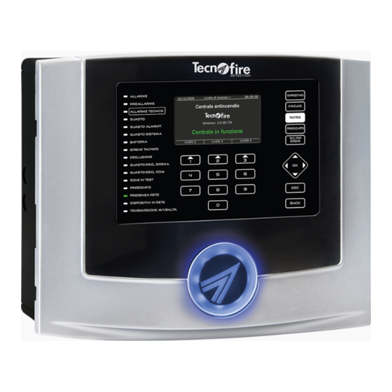
5 - USER INTERFACE 5-1 - Control panel The user interface of the control panel consists of a 480 x 272 pixels TFT color graphic display, 16 notifi cation LED, 5 function keys, 7 navigation keys and 10 number keys, with which the user can manage the system. The user interface is completed by the speaker that, according to the functional states of the control panel, provides audible alarms or notifi... -
Page 20: Function Keys
ACCESS TO ACCESS LEVELS Access level 1 is not protected by code Access level 1 08:00:00 16/02/2019 Access level 2 Fire control panel Access level 3 Release: 2.0.00 ENG Control panel working Level 2 Level 3 Level 4 Access level 4 5-3 - Function keys The table describes the keys on the front panel of the control panel. - Page 21 5-4 - Signaling LED The table describes the functions and procedures for reporting of the LED on the front panel of the control panel. As required by EN 54-2 provisions concerning light signals, the ON/OFF fl ashing frequency of the LED is: •...
- Page 22 5-5 - Viewing of operating states The display changes the display mode according to the operating state of the control panel, stand-by, active event and active acknowledged event. 16/02/2019 Access level 1 08:00:00 Stand-by state The display shows the date and time, the access level, Fire control panel the description given to the control panel, the fi...
- Page 23 EVENT STORAGE FOLDERS Name Icon Description Name Icon Description Alarm The folder logs and counts all fi re alarms Failure The folder logs and counts all zone and system failures 0000 divided by zone 0000 Preal. The folder logs and counts all fi re prealarms Excl.
- Page 24 5-6 - Notifi cation of operating states The operating states of the control panel are notifi ed optically and acoustically and according to the level of priority (see below table). Priority level Operating state Priority level Operating state Fire alarm Technical prealarm Fire prealarm Failure...
-
Page 25: Technical Alarm
TECHNICAL PRELARM STATE A technical double-knock zone in alarm or a detector in prealarm state. The speaker issues the audible prealarm signal 16/02/2019 Access level 1 08:00:00 The TECHNICAL ALARM LED fl ashes Signaling before acknowledgment The output programmed for technical prealarm is triggered Technical prealarm The display shows the technical prealarm state The speaker is muted... - Page 26 5-7 - Icons The below table illustrates the icons that the control panel uses to optically support the notifi cation of its operating states, alarms, failures etc. ICONS Battery charger failure No mains power This icon signals that the power supply is not able to charge This icon signals power failure.
-
Page 27: System Failures
6 - FAILURE NOTIFICATIONS The control panel manages two types of failures: system failures and general failures. System failures are a special category of failures that refer to the standard EN 54-2. General failures group all the other types of failures. 16/02/2019 Access level 1 08:00:00... - Page 28 TFA2-596 - TFA4-1192...
-
Page 29: Power Supply
7 - POWER SUPPLY 1 - Composition The power supply section of the control panel complies with the requirements of the standard EN 54-4. It consists of a primary power supply (PS - power supply) and a secondary power supply (SD - storage device). The primary power supply consists of a modular switching power supply, capable of providing 5A/28V direct current. - Page 30 7-1 - Failure notifi cations of the power supply section TABLE 1 - PRIMARY POWER SUPPLY FAILURE The test is performed every second. The failure is notifi ed when for the preset time the mains power is missing. Test frequency 1 second Delay of failure notifi...
- Page 31 TABLE 4 - BATTERY CHARGER FAILURE The test is performed every second. The failure is notifi ed when the test detects for more than 5 minutes the presence of mains power, but not the battery charging current. Test frequency 1 second Delay of failure notifi...
- Page 32 TFA2-596 - TFA4-1192...
-
Page 33: Detection Zones
8 - DETECTION ZONES 8-1 - Zones The 199 detectors and 99 modules that can be connected to the control panel's detection loop must be assigned to the zones of the control panel. The devices not assigned to any zone, will be automatically assigned to the default zone. ZONE CONFIGURATION RULES It can include only detectors It can include only modules... -
Page 34: Fire Zones
8-2 - Fire zones Single-knock fi re zone The alarm of a single device (single-knock) is suffi cient to generate the alarm of the zone and initiate the alarm procedure programmed for the zone and the evacuation siren. If a device generates a prealarm, the zone will switch to prealarm state. SINGLE-KNOCK FIRE ZONE - PREALARM TRIGGERING Prealarm Alarm... - Page 35 DOUBLE-KNOCK FIRE ZONE - ALARM TRIGGERING FROM A MANUAL CALL POINT Alarm No alarm An alarm from a manual call point in alarm state (pressed) The zone is in stand-by state immediately triggers the alarm notifi cations FIRE ZONE - BEHAVIOR AFTER PREALARM Prealarm No alarm state stops...
- Page 36 8-3 - Technical zones The prealarm and alarm outputs of the technical zone must be programmed, specializing the programmable outputs for these functions. Single-knock technical zone The alarm of a single device (single-knock) is enough to generate a technical alarm of the zone and trigger the output specifi cally programmed for technical alarm.
- Page 37 TECHNICAL ZONE - BEHAVIOR AFTER PREALARM Prealarm state No alarm stops No alarm Technical prealarm Prealarm state Technical prealarm None continues Flag Prealarm Behavior Prealarm timeout after prealarm timeout expired Zone switches Technical alarm Alarm to alarm A device in prealarm state Double-knock Behavior On the basis of the setting,...
- Page 38 8-4 - Monitored system mode Warning: the monitored system mode may only be used if the control panel is under the direct control of authorized personnel. It is only available if its use was enabled during setup. The activation and deactivation of the monitored system mode requires a level 2 code. Its activation is indicated by the relevant LED on the control panel which turns on.
- Page 39 MONITORED SYSTEM MODE - ALARM TRIGGERING FROM A MANUAL CALL POINT Alarm No alarm An alarm from a manual call point in alarm state (pressed) The zone is in stand-by state immediately triggers the alarm notifi cations TFA2-596 - TFA4-1192...
- Page 40 TFA2-596 - TFA4-1192...
-
Page 41: Electronic Boards
9 - ELECTRONIC BOARDS The control panel electronics are divided into two parts, the CPU board and the terminal board. 9-1 - TFA2-596 terminals Ethernet CPU board Power supply Battery connector connector connector connection JP1 BATT TFA2-596 F1 5A - F RJ45 NC NA NC NA... - Page 42 9-2 - Terminals Outputs Notes Max. current Common contact Normally closed contact Alarm relay output with free contact 30V DC Normally open contact Common contact Normally closed contact Failure relay output with free contact 30V DC Normally open contact NC NA NC NA NC NA C NC NA...
-
Page 43: Programmable Outputs
Loop Notes Max. current Negative power supply voltage for line 2A Outward loop Positive power supply voltage for line 2A 500mA 24V DC Negative power supply voltage for line 2B Return loop Positive power supply voltage for line 2B Master Bus Notes Max. - Page 44 9-3 - TFA4-1192 terminals Ethernet CPU board Power supply Battery connector connector connector connection JP1 BATT TFA4-1192 F1 5A - F RJ45 NC NA NC NA NC NA C NC NA NA NA OUT4 OUT6 FAULT OUT1 OUT2 OUT3 RESET OUT5 Warning: the outputs OUT1 (terminals 7, 8, 9), OUT2 (terminals 10, 11, 12), OUT3 (terminals 13, 14, 15),OUT4 (terminal 20), OUT5 (terminal 21), OUT6 (terminal 22), alarm relay otput ALL (terminals 1, 2, 3) and the relay output RESET (terminals 16, 17)
- Page 45 9-4 - Terminals Outputs Notes Max. current Common contact Normally closed contact Alarm relay output with free contact 30V DC Normally open contact Common contact Normally closed contact Failure relay output with free contact 30V DC Normally open contact NC NA NC NA NC NA C NC NA...
- Page 46 Loop Notes Max. current Negative power supply voltage for line 2A Outward loop Positive power supply voltage for line 2A 500mA 24V DC Negative power supply voltage for line 2B Return loop Positive power supply voltage for line 2B Loop Notes Max.
-
Page 47: Cpu Board
9-5 - CPU board The CPU board is equipped with all the key jumpers which permit high-level management of the control panel, such as fi rmware upgrade, reset of system confi guration, access to the 4th (manufacturer) access level etc. The CPU board also hosts the USB and TTL ports for connecting a PC and a serial printer to the control panel. - Page 48 The USB port allows to connect the control panel directly to a PC, for programming of the control panel and upgrade of its fi rmware. This connection supports only the standard Tecnofi re protocol from the Tecnoalarm and TECNOMONITOR software.
-
Page 49: Input Protection
9-6 - Power supply The control panels are equipped with a Fly-back type switching power supply model ALSW285PFC providing a maximum output current of 5A @ 24V DC (default calibration 28.8V DC @ 25°C). The power supply is equipped with an integrated PFC circuit (Power Factor Correction) which interrupts current supply when there is no power demand. - Page 50 TFA2-596 - TFA4-1192...
- Page 51 10 - CONNECTION This chapter explains how to connect the detection loop, the sirens and the Master Bus. N.B. All detectors and modules connectable on the loop are equipped with a dual loop isolator (inbound and outbound), in compliance with the standard EN 54-2 which provides for an isolator at least every 32 devices. 10-1 - Detection loop connection On the detection loop of the control panel it is possible to connect up to 199 detectors and up to 99 modules.
-
Page 52: Siren Connection
Open loop connection 10-2 - Siren connection The sirens are connected via a controlled output (terminals 25 SIR+ and 26 SIR-). The line must must be terminated with a 47K resistance: • If no siren is connected, a 47K bus termination resistor must be connected between terminals 25 and 26. •... -
Page 53: Rs485 Bus Connection
10-3 - RS485 bus connection The control panel provides two RS485 ports used to connect a total of 16 expansion devices. The same serial ports can be used to connect other control panels creating a network of maximum 16 control panels. The master and slave bus can be connected in open or closed loop mode. - Page 54 Closed loop connection to Master control panel - Master control panel - Slave control panel - Bus termination - Bus continues - Jumpers inserted - Jumpers open - Repeater - Repeater - Bus continues - Bus continues - SW1.1 OFF - SW1.1 OFF - Slave control panel - Bus continues...
- Page 55 Connection of repeaters in open loop to Master control panel with fi ber optic converter. - Repeater - Repeater - Bus termination - Bus continues - SW1.1 ON - SW1.1 OFF 1 OFF 1 OFF 2 ON 2 OFF 3 ON 3 OFF 4 ON 4 OFF...
- Page 56 10-4 - Potentiation of the secondary power supply Normative references The European standards indicate the conditions and parameters necessary to dimension the secondary power supply on the basis of the current requirements. The secondary power supply shall be dimensioned to ensure, in the event of main power failure, the autonomous operation of the system.
- Page 57 10-6 - TFA4-1192 additional power supply connection Connection of one or two additional power supplies The outputs OUT A, OUT B and OUT C of each TFPS-5 power supply must be connected in parallel and must then be connected one to the terminals 29 and 30 and the other to the terminals 31 and 32 of the control panel. TFPS-5 - No.
- Page 58 10-7 - Telephone communicator The electronics of the TFCOM telephone communicator are divided into two parts, the CPU board and the LED board. RS485 Port Port LED USB BOOT PROG RESET LED board connector LED RUN LED LINE JP10 BATT BATTERY RS485 serial bus Notes...
- Page 59 Signaling LED RUN Green Flashing = normal operatiing conditions LED LINE On = PSTN telephone line busy LED USB On = USB cable connected END-OF-SERIAL BUS Insert on the last device of the serial bus PROTECTION AGAINST DEEP DISCHARGE Automatic battery disconnection for Vbat <8.9V DC Protection against deep discharge disabled Key jumpers Special high-level procedures, such as fi...
- Page 60 10-8 - External Ethernet interface *2903000024* *2903000024* TFNET 121016 RJ45 TECNO OUT DDNS RS485 MODBUS Positive power supply voltage for serial bus Not connected (terminal not used) Negative power supply voltage for serial bus Negative reference voltage Channel A serial bus Channel A Modbus Channel B serial bus Channel B Modbus...
- Page 61 10-9 - Repeaters Terminals Description Signal Positive power supply voltage for serial bus +24V DC Negative power supply voltage for serial bus Channel A serial bus Serial Channel B serial bus Serial Cable shield connection Bus termination Bus terminated (only if last device) Bus not terminated (only if not last device) Unused (reserved) BOOT function...
- Page 62 NOTES TFA2-596 - TFA4-1192...
- Page 64 ISO 9001 Via Ciriè, 38 - 10099 - San Mauro T. se - Torino (Italy) - Manufacturing plant: Strada del Cascinotto, 139/54 10156 Torino (Italy) Tel. +39 011 22 35 410 - Fax +39 011 27 35 590 - info@tecnofi redetection.com - www.tecnofi redetection.com...
Need help?
Do you have a question about the Tecnofire TFA2-596 and is the answer not in the manual?
Questions and answers