
Related Manuals for ADLINK Technology NEON-2000-JT2-X Series


Summary of Contents for ADLINK Technology NEON-2000-JT2-X Series
- Page 1 NEON-2000-JT2-X Series AI Smart Camera User’s Manual Manual Rev.: Revision Date: October 27, 2020 Part No: 50-1Z338-1000 Leading EDGE COMPUTING...
- Page 2 Leading EDGE COMPUTING Revision History Revision Release Date Description of Changes 2020-10-27 Initial version Revision History...
-
Page 3: Preface
NEON-2000-JT2-X Preface Copyright © 2020 ADLINK Technology, Inc. This document contains proprietary information protected by copy- right. All rights are reserved. No part of this manual may be repro- duced by any mechanical, electronic, or other means in any form without prior written permission of the manufacturer. - Page 4 Leading EDGE COMPUTING Conventions Take note of the following conventions used throughout this manual to make sure that users perform certain tasks and instructions properly. Additional information, aids, and tips that help users perform tasks. NOTE: NOTE: Information to prevent minor physical injury, component dam- age, data loss, and/or program corruption when trying to com- plete a task.
-
Page 5: Table Of Contents
NEON-2000-JT2-X Table of Contents Revision History..............ii Preface ..................iii List of Figures ............... vii List of Tables................ix 1 Introduction ................ 1 Overview................1 Features................2 General Specifications............3 Mechanical Dimensions............5 1.4.1 Camera Dimensions ........... 5 Accessories ................. 6 2 Connectors and I/O ............ - Page 6 Leading EDGE COMPUTING 3.5.2 Inference Concepts and Sample Code..... 24 3.5.3 Image Inference Procedure ........24 Using the Basler pylon Utility ..........26 3.6.1 Capturing Images in pylon ........26 3.6.2 Modifying Image Sensor Settings in pylon....29 3.6.3 Using APIs to Modify Image Sensor Settings ... 33 4 Software Upgrade .............
-
Page 7: List Of Figures
NEON-2000-JT2-X List of Figures Figure 2-1: NEON-2000-JT2-X Orientation........7 Figure 2-2: Bottom Side I/O and Connectors ........8 Figure 2-3: DI/O M12 17-Pin Connector ..........9 Figure 2-4: LAN Connector .............. 11 Figure 2-5: Top Side LED Indicators..........12 Figure 2-6: Front Side Components..........13 Figure 3-1: NEON-2000-JT2-X Mounting Holes ...... - Page 8 Leading EDGE COMPUTING This page is intentionally left blank. viii List of Figures...
-
Page 9: List Of Tables
NEON-2000-JT2-X List of Tables Table 1-1: NEON-2000-JT2-X Model and Sensor Specifications 1 Table 1-2: NEON-2000-JT2-X Starter Kit Contents..... 6 Table 2-1: Bottom Side Connectors and Functions ..... 8 Table 2-2: DI/O M12 17-Pin Connector Pin Definitions ..... 10 Table 2-3: DI/O Connector Specifications ......... - Page 10 Leading EDGE COMPUTING This page is intentionally left blank. List of Tables...
-
Page 11: Introduction
NEON-2000-JT2-X Introduction 1.1 Overview The NEON-2000-JT2-X series is an open camera platform ® equipped with an NVIDIA Jetson™ TX2 module to support a series of image sensors that provide industrial DI/O and image capture and inference capabilities. The NEON-2000-JT2-X is... -
Page 12: Features
Leading EDGE COMPUTING 1.2 Features IP67 (Ingress Protection)-certified, suited for harsh environ- ments Pre-installed operating system, drivers, and utilities; deep learning sample code; plug and play NVIDIA Jetson TX2 and dual-core NVIDIA Denver 2 + quad-core ARM Cortex-A57, 8GB 128-bit LPDDR4 memory and integrated 256-core Pascal GPU ... -
Page 13: General Specifications
NEON-2000-JT2-X 1.3 General Specifications Lens mount: C-mount Total weight: 900g (with lens protector, without lens) Operating temperature: 45°C (tested when running YOLOv4; airflow 0.6 m/s) Power consumption: <35W Compute module: NVIDIA Jetson TX2 CPU: ARM Cortex-A57 MPCore (quad-core) and NVIDIA Denver 2 (dual-core) ... - Page 14 Leading EDGE COMPUTING NEON- NEON- NEON- NEON- 201B-JT2-X 202B-JT2-X 203B-JT2-X 204B-JT2-X Compute Module NVIDIA® Jetson™ TX2 Processor ARM Cortex-A57 and NVIDIA Denver 2 Display Output DisplayPort over USB Type-C, 1920x1080 @ 30fps Image Sensor 1280x960 1600x1200 1920x1080 2592x1944 Resolution Image Sensor Size 1/3”...
-
Page 15: Mechanical Dimensions
NEON-2000-JT2-X 1.4 Mechanical Dimensions This section provides dimensions and related mechanical informa- tion for the NEON-2000-JT2-X. 1.4.1 Camera Dimensions Dimensions: mm Introduction... -
Page 16: Accessories
Leading EDGE COMPUTING 1.5 Accessories ADLINK provides all the necessary parts and accessories for the NEON-2000-JT2-X in the starter kit. You can purchase individual accessories according to your needs. The following table provides details about each item. Item Specification/Description Part Number ... -
Page 17: Connectors And I/O
NEON-2000-JT2-X Connectors and I/O This chapter includes the locations and descriptions of the connectors and I/O on the NEON-2000-JT2-X. Top Side Top Side Front Side Back Side Bottom Side Bottom Side Figure 2-1: NEON-2000-JT2-X Orientation Connectors and I/O... -
Page 18: Bottom Side I/O And Connector Description
Leading EDGE COMPUTING 2.1 Bottom Side I/O and Connector Description Figure 2-2: Bottom Side I/O and Connectors Item Description IP67 USB Type-C connector for power, DisplayPort, and USB 3.0 IP67 M12 17-pin connector for DC 24V input, 2x DI/O, and 1x RS-232 IP67 M12 8-pin connector for Gigabit Ethernet Table 2-1: Bottom Side Connectors and Functions DC power can be supplied from either the USB Type-C port or... -
Page 19: Di/O Connector Pin Definitions
NEON-2000-JT2-X 2.1.1 DI/O Connector Pin Definitions Figure 2-3: DI/O M12 17-Pin Connector Pin Type Description Bi-DIR USB 2.0 D+ (for flashing the TX2) Input DC 24V input Input DC 24V input Input Digital input 0/Trigger input 0 (see Note 1) Output Digital output 0/Strobe output 0 (see Note 2) Output... -
Page 20: Table 2-2: Di/O M12 17-Pin Connector Pin Definitions
Leading EDGE COMPUTING Pin Type Description Input Digital input 1 Input RS-232 RXD (PC>NEON) Output RS-232 TXD (NEON>PC) Input TX2 reset Table 2-2: DI/O M12 17-Pin Connector Pin Definitions 1. Pin 4 (Digital input 0/Trigger input 0) is programmable. When configured for trigger input, pin 4 is used for hardware trigger- ing of the image sensor. -
Page 21: Lan Connector Pin Definitions
NEON-2000-JT2-X 2.1.2 LAN Connector Pin Definitions Figure 2-4: LAN Connector Description MDI2- MDI3+ MDI3- MDI0- MDI1+ MDI0+ MDI2+ MDI1- Table 2-4: LAN Connector Pin Definitions Connectors and I/O... -
Page 22: Top Side Led Indicators
Leading EDGE COMPUTING 2.2 Top Side LED Indicators Figure 2-5: Top Side LED Indicators Function Description Red: Ethernet is active Green: 100/1000 Mbps Ethernet status indicator Orange (Red/Green): Ethernet is working normally Red: System is ready ... -
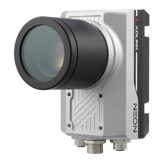
Page 23: Front Side Description
NEON-2000-JT2-X 2.3 Front Side Description Figure 2-6: Front Side Components Item Description C-mount type lens mount Image sensor Lens protector mounting thread (Metric thread: M60x1.5mm) Table 2-6: Front Side Description Connectors and I/O... - Page 24 Leading EDGE COMPUTING This page is intentionally left blank. Connectors and I/O...
-
Page 25: Getting Started
NEON-2000-JT2-X Getting Started 3.1 Mounting the Device The NEON-2000-JT2-X can be mounted using the mounting screw holes on either the front (A) or back (B) sides. Le NEON-2000-JT2 peut être monté à l'aide des trous de vis de montage sur les côtés avant (A) ou arrière (B). Figure 3-1: NEON-2000-JT2-X Mounting Holes Getting Started... -
Page 26: Din Rail Mount
Leading EDGE COMPUTING 3.1.1 DIN Rail Mount You can purchase a DIN rail kit and related accessories from ADLINK (P/N: 91-95281-000E). Figure 3-2: DIN Rail Mount (Separated) Figure 3-3: DIN Rail Mount (Assembled) Getting Started... -
Page 27: Digital I/O Connections
NEON-2000-JT2-X 3.2 Digital I/O Connections External devices such as trigger sensors, LED light controllers and relays can be connected to the NEON-2000-JT2-X to implement different applications. This section shows how to connect such devices. Figure 3-4: Digital Input Schematic Diagram Figure 3-5: Digital Output Schematic Diagram Getting Started... -
Page 28: Attaching A Lens
Leading EDGE COMPUTING 3.3 Attaching a Lens The NEON-2000-JT2-X is compatible with C-mount type lenses. Figure 3-6: Lens Attachment Assembly The transfer ring is preinstalled. The washer is used only with the NEON-202B-JT2-X. NOTE: NOTE: Getting Started... -
Page 29: Power And Peripheral Connections
NEON-2000-JT2-X 3.4 Power and Peripheral Connections The NEON-2000-JT2-X can be powered from either a USB Type- C adapter or the DI/O M12 17-pin connector (24V DC input). The USB Type-C connector also supports DisplayPort video signal and USB 3.0, which can be used to connect a keyboard and mouse. The following figures show examples of power and peripheral con- nection configurations. -
Page 30: Figure 3-8: Powered By Usb Type-C Hub/Adapter
Leading EDGE COMPUTING RS-232 Devices External I/O Devices DI/O Cable DIN-37-01 USB Type-C Cable USB Type-C AC Power Hub/Adapter HDMI Monitor USB Keyboard & Mouse This configuration requires an ADLINK USB Type-C hub/ adapter (P/N 92-99090-1010). Do not supply power to the camera from the AC/DC adapter NOTE: NOTE: and the USB Type-C hub/adapter at the same time. -
Page 31: Image Capture And Inference
NEON-2000-JT2-X 3.5 Image Capture and Inference ADLINK provides sample code files for testing the built-in Basler image capturing and inference functions on the NEON-2000-JT2-X. This section describes how to execute the classification sample code with the NEON-2000-JT2-X. 3.5.1 Executing the Sample Code 1. - Page 32 Leading EDGE COMPUTING ./build/aarch64/bin/imagenet-camera 1920 1080 Image capture and inference results will appear in a new window, with the inference result in the upper-left corner. Getting Started...
- Page 33 NEON-2000-JT2-X You can also modify the Sensor_width and Sensor_height settings in the pylon Viewer utility. For details, see Modifying Image Sensor Settings in pylon. Getting Started...
-
Page 34: Inference Concepts And Sample Code
Leading EDGE COMPUTING 3.5.2 Inference Concepts and Sample Code This section illustrates the main concepts of inference with sample files and also provides a link to examples from NVIDIA. The default path of the sample files is /home/Desktop/Capture_and_ Inference_Sample. The following folders and files in this directory are essential for image capture and inference tasks: ... - Page 35 NEON-2000-JT2-X Make sure to create an inference model before using it. This sam- ple uses ImageNet as an example. 3. Start streaming. In this sample, the NEON-2000-JT2-X is in free run mode and frames are passed one at a time. You can set the pixel format of the camera output to RGB mode in pylon Viewer via Features >...
-
Page 36: Using The Basler Pylon Utility
Leading EDGE COMPUTING 3.6 Using the Basler pylon Utility This section describes how to use the Basler pylon utility to cap- ture images and adjust, load, and save sensor settings. 3.6.1 Capturing Images in pylon The following steps illustrate how to capture images using the Basler pylon Viewer application. - Page 37 NEON-2000-JT2-X 3. Click the Single Shot or Continuous Shot button to capture images. Single Shot Continuous Shot Getting Started...
- Page 38 Leading EDGE COMPUTING The camera will capture images and display activity according to the selected option. Single Shot Continuous Shot Getting Started...
-
Page 39: Modifying Image Sensor Settings In Pylon
NEON-2000-JT2-X 3.6.2 Modifying Image Sensor Settings in pylon The default NEON-2000-JT2-X image sensor settings may not be suitable for all applications. This section illustrates how to modify image sensor settings in the Basler pylon utility. 1. Click the pylon Viewer icon. 2. - Page 40 Leading EDGE COMPUTING 3. Click Camera > Load Features... 4. Select the desired *.pfs file and click Open to load the sensor settings. Getting Started...
- Page 41 NEON-2000-JT2-X The image sensor settings will update and appear under Features in the main window. 5. Modify the image sensor settings as needed. 6. Click Camera > Save Features. Getting Started...
- Page 42 Leading EDGE COMPUTING 7. Select a location, specify a name for the *.pfs file, and click Save to save the sensor settings. Getting Started...
-
Page 43: Using Apis To Modify Image Sensor Settings
NEON-2000-JT2-X 3.6.3 Using APIs to Modify Image Sensor Settings After opening the device, you can add the PylonFeaturePersis- tenceLoad function to load features and modify the image sensor settings. You can find supporting documentation and additional sample code in the following directories: •... - Page 44 Leading EDGE COMPUTING This page is intentionally left blank. Getting Started...
-
Page 45: Software Upgrade
NEON-2000-JT2-X Software Upgrade Each NEON-2000-JT2-X comes with Ubuntu and Jetpck pre- installed. ADLINK builds custom flash files to upgrade the NEON- 2000-JT2-X based on NVIDIA’s release schedule. Important Notice NVIDIA official operating system releases for the Jetson TX2 development kit CANNOT be used on the NEON-2000-JT2-X. Be sure to upgrade the NEON-2000-JT2-X with an operating system or flash file ONLY from ADLINK. -
Page 46: System Flashing Equipment
Leading EDGE COMPUTING 4.1.1 System Flashing Equipment The following table lists the required tools for flashing the NEON- 2000-JT2-X OS image. Item Description Note Minimum requirements: Intel® Core™ i3 CPU, 4 GB DDR and 1x Host PC 128 GB of free SSD/HDD space. ... -
Page 47: System Flashing Procedure
NEON-2000-JT2-X 4.1.2 System Flashing Procedure This section illustrates how to flash the NEON-2000-JT2-X OS image. Ensure that you have obtained the correct image file from ADLINK and have saved it to the host PC before performing the following procedure. 1. Connect the M12 17-pin connector (male) on the system flash cable to the DI/O input on the bottom side of the NEON-2000-JT2-X. - Page 48 Leading EDGE COMPUTING 8. Navigate to the directory containing the flash file and execute the flash script to begin the flashing process. cd Linux_for_Tegra.NEON.32.2_20190828/bootloader sudo ./multi_tegra_flash.sh The names of the directory and flash file in this example are for illustration only. Directory and flash file names will vary accord- ing to your system configuration and the specific flash file used.
-
Page 49: Important Safety Instructions
NEON-2000-JT2-X Important Safety Instructions For user safety, please read and follow all instructions, Warnings, Cautions, and Notes marked in this manual and on the associated device before handling/operating the device, to avoid injury or damage. Read these safety instructions carefully ... - Page 50 Leading EDGE COMPUTING A Lithium-type battery may be provided for uninterrupted backup or emergency power. Risk of explosion if battery is replaced with one of an incorrect type; please dispose of used batteries appropriately. CAUTION: The device must be serviced by authorized technicians when: ...
-
Page 51: Consignes De Sécurité Importante
NEON-2000-JT2-X Consignes de Sécurité Importante S'il vous plaît prêter attention stricte à tous les avertissements et mises en garde figurant sur l'appareil, pour éviter des blessures ou des dommages. Lisez attentivement ces consignes de sécurité. Conservez le manuel de l'utilisateur pour pouvoir le consulter ultérieurement. - Page 52 Leading EDGE COMPUTING tenu que par du personnel technique qualifié à l'aide d'outils appropriés. Une batterie de type lithium peut être fournie pour une alimen- tation de secours ou une alimentation de secours ininterrom- pue. Risque d’explosion si la pile est remplacée par une autre de type incorrect.
-
Page 53: Getting Service
San Jose, CA 95138, USA Tel: +1-408-360-0200 Toll Free: +1-800-966-5200 (USA only) Fax: +1-408-360-0222 Email: info@adlinktech.com ADLINK Technology (China) Co., Ltd. 300 Fang Chun Rd., Zhangjiang Hi-Tech Park Pudong New Area, Shanghai, 201203 China Tel: +86-21-5132-8988 Fax: +86-21-5132-3588 Email: market@adlinktech.com...
Need help?
Do you have a question about the NEON-2000-JT2-X Series and is the answer not in the manual?
Questions and answers