Advertisement
Available languages
Available languages
Quick Links
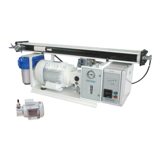
YC & YK
MANUEL UTILISATEUR P3
Tous voltages 115V – 230V – 400V / 50 & 60Hz / Monophasé & Triphasé
OWNER MANUAL P9
All Voltages 115V – 230V – 400V / 50 & 60Hz / Single phase & Three phases
GUÍA DE MONTAJE Y DE MANTENIMIENTO P15
Todas voltajes 115V – 230V – 400V / 50 & 60Hz / Monophasico & Triphasicos
ATTENTION : Lisez attentivement l'intégralité de cette documentation, avant d'installer, d'utiliser ou d'entretenir le dessalinisateur
AQUA-BASE. Vous éviterez ainsi les désagréments d'une opération incorrecte, dont les conséquences ne seraient pas couvertes par la
garantie.
WARNING : Read this documentation carefully in its entirety, before installation, use or maintenance of the AQUA-BASE desalination unit.
In this way you will avoid incorrect operating faults which may lead to consequences that will not be covered by the guarantee.
ATENCIÓN : Por favor, leer detenidamente las siguientes instrucciones antes de instalar, utilizar o limpiar el osmotizador AQUA-BASE.
De esta forma, evitará los errores de una instalación incorrecta y sus consecuencias no cubiertas por la garantía.
F R / G B / E S Page 1/1
VERSION 01/07
AQUABASEYFR-GB-ES 01-2007
Advertisement

Related Manuals for Aqua-Base YC


Summary of Contents for Aqua-Base YC
- Page 1 WARNING : Read this documentation carefully in its entirety, before installation, use or maintenance of the AQUA-BASE desalination unit. In this way you will avoid incorrect operating faults which may lead to consequences that will not be covered by the guarantee.
- Page 2 F R / G B / E S Page 2/2 VERSION 01/07 AQUABASEYFR-GB-ES 01-2007...
- Page 3 ATTENTION : Lisez attentivement l’intégralité de cette documentation, avant d’installer, d’utiliser ou d’entretenir le dessalinisateur AQUA-BASE. Vous éviterez ainsi l es désagréments d’une opération incorrecte, dont les conséquences ne seraient pas couvertes par la garantie. SOMMAIRE Page Chapitre Présentation Caractéristiques Description Circuit d’eau et circuit électrique, schéma synoptique...
- Page 4 La pompe BP doit être installée au dessous de la flottaison, le plus près possible de la vanne de coque. Version YK en kit Version YC compacte - Le module principal doit - Le filtre doit être installé verticalement sur une paroi, au moyen du support dont il est équipé. En cas de nécessité, il est toutefois possible de l’incliner légèrement par rapport à...
- Page 5 5. OPTIONS 51. COMMANDE A DISTANCE Cette option permet de commander et surveiller l’appareil AQUA-BASE à partir d’un endroit distant de l’appareil, table à carte, tableau électrique principal. Composition. La commande à distance est composée d'un coffret encastrable muni du tableau de commande et d'un câble de liaison.
- Page 6 EXEMPT DE TOUTE TRACE DE CORPS GRAS. Remplir le seau de 10l d’eau produite par l’appareil AQUA-BASE ou à défaut d'eau douce non chlorée; pour déchlorer l'eau du réseau il suffit d'y ajouter un peu de produit de stockage AQUA-BASE Réf. 752039.
- Page 7 8. ENTRETIEN L'appareil AQUA-BASE doit être entretenu régulièrement, afin d'éviter la naissance ou la persistance d'anomalies qui pourraient altérer son efficacité, son fonctionnement et sa fiabilité. La périodicité d'entretien de l'appareil AQUA-BASE dépend de la fréquence et des conditions d’utilisation.
- Page 8 87. NETTOYAGE DES MEMBRANES En fonctionnement normal, les membranes d'osmose inverse s’encrassent par des dépôts minéraux et organiques, qui s'accumulent jusqu'à causer une baisse de la quantité et de la qualité de l’eau produite. Les membranes doivent être nettoyées chaque fois que la quantité ou la qualité de l’eau produite dérive de façon excessive.
- Page 9 WARNING : Read this documentation carefully in its entirety, before installation, use or maintenance of the AQUA-BASE desalination unit. In this way you will avoid incorrect operating faults which may lead to consequences that will not be cove red by the guarantee.
- Page 10 - The booster pump should be installed below the water line, as near of the hull valve as possible. Range YK in kit form Range YC in compact - The filters should be fixed vertically in place, by means of the equipped support.. If necessary, it can be slightly inclined in relation to form the vertical position.
- Page 11 44. ELECTRICAL CONNECTION (See electric drawings fig 7p30, 16p34 & 17p35) WARNING : - the AQUA-BASE unit is equipped with circuit breakers insuring its protection and security. This doesn’t insure the protection of your installation which should be equipped with devices conforming to the current legislation.
- Page 12 FREE OF ANY TRACES OF GREASY SUBSTANCE. Fill the bucket with 10l of water produced by the AQUA-BASE unit, or failing this, unchlorinated fresh water; to dechlorinate mains water, just add a pinch of preservation solution AQUA-BASE, reference 752039.
- Page 13 8. MAINTENANCE The AQUA-BASE unit must be maintained regularly in order to avoid the occurrence of defects which could alter its efficiency, its operating and its reliability. The intervals between maintenance of the AQUA-BASE unit depend on the frequency and conditions of use.
- Page 14 87. CLEANING OF THE MEMBRANES In normal operating, the R/O membranes can be clogged by mineral and organic deposits which accumulate until they cause a drop in fresh water production quality and quantity. The membranes should be cleaned each time the quantity or the quality of the produced water changes excessively. Before proceeding with membranes cleaning check that the change in performances has no other cause, such as: - Low sea water temperature: refer to the temperature/production curve, - Filter clogged, water system badly drained, leading to lack of water at the HP pump,...
- Page 15 El Servicio AQUA-BASE 1. PRESENTACIÓN El osmotizador AQUA-BASE serie Y está disponible en versión kit YK, o en versión compacta YC. La versión kit AQUA-BASE YK se presenta en módulos disociados : En la versión compacta AQUA-BASE YC, los distintos - bomba de alimentación en agua de mar de baja presión y desagüe correspondiente,...
- Page 16 - La bomba BP se debe instalar debajo de la línea de flotación, lo más cerca posible de la válvula de casco. Versión YK en kit Versión YC compacta - El filtro se debe instalar verticalmente sobre un mamparo, mediante el soporte del cual está equipado. En caso de necesidad, es posible - El módulo principal...
- Page 17 44. CONEXIÓN ELÉCTRICA (Ver esquema eléctrico 7p30, 16p34 & 17p35) ATENCIÓN : - El aparato AQUA-BASE está equipado de relés térmicos asegurando su protección y su seguridad. Sin embargo, éste no protege su instalación que será equipada de los dispositivos requeridos por la legislación vigente.
- Page 18 TODO CUERPO GRASO. 1. Llenar el recipiente auxiliar de 10 l de agua producida por el AQUA-BASE o por defecto, de agua dulce sin cloro, para quitar el cloro de la red, solo basta con añadir un poco de producto de almacenaje AQUA-BASE Ref.
- Page 19 8. MANTENIMIENTO El aparato AQUA-BASE debe tener un mantenimiento periódico, de forma que evite la aparición o la persistencia de anomalías que podrían alterar su eficacia, su funcionamiento o su fiabilidad. La periodicidad de mantenimiento del AQUA-BASE depende de la frecuencia y de las condiciones de utilización.
- Page 20 87. LIMPIEZA DE LAS MEMBRANAS Con un funcionamiento normal, las membranas de osmosis se ensucian con residuos minerales y orgánicos que se acumulan hasta causar una disminución de la cantidad y de la calidad de agua producida. Las membranas se deben limpiar cada vez que la cantidad o calidad de agua producida cambia de forma excesiva.
- Page 21 AQUA-BASE, puis retourné à l’usine à l N° de série adresse suivante : Series N° N° de série WARNING: This REPORT should be completed after starting up of the AQUA-BASE unit, then returned to the factory at the following Tension Voltage address : Voltaje Options ATENCIÓN:...
- Page 22 F R / G B / E S Page 22/22 VERSION 01/07 AQUABASEYFR-GB-ES 01-2007...
- Page 23 3-way valve connector CONECTADOR DE VÁLVULA 3 VÍAS 719183 Clapet anti retour FF1/4G Check valve FF1/4G VÁLVULA ANTI-RETORNO FF1/4G 700657 Châssis AQUABASE-YC Frame AQUABASE-YC BASTIDOR AQUABASE-YC F R / G B / E S Page 23/23 VERSION 01/07 AQUABASEYFR-GB-ES 01-2007...
- Page 24 ENCOMBREMENT / GENERAL LAY OUT / DIMENSIONES Fig 1 F R / G B / E S Page 24/24 VERSION 01/07 AQUABASEYFR-GB-ES 01-2007...
- Page 25 ENCOMBREMENT / GENERAL LAY OUT / DIMENSIONES ® Fig 1bis F R / G B / E S Page 25/25 VERSION 01/07 AQUABASEYFR-GB-ES 01-2007...
- Page 26 DESCRIPTIF / DESCRIPTION / DESCRIPTION Fig. 18 (Ch31) AQUA-BASE YK 4-20 Fig. 19 (Ch31) F R / G B / E S Page 26/26 VERSION 01/07 AQUABASEYFR-GB-ES 01-2007...
- Page 27 SYSTEME FLUSH / FLUSH SYSTEM / FLUSH SISTEM Fig. 21 Fig. 22 F R / G B / E S Page 27/27 VERSION 01/07 AQUABASEYFR-GB-ES 01-2007...
- Page 28 SYNOPTIQUE/FLOW CHART/SINÓPTICO AQUA-BASE YC-YK 4-20 Fig. 2 (Ch31) Fig. 3 (Ch32) F R / G B / E S Page 28/28 VERSION 01/07 AQUABASEYFR-GB-ES 01-2007...
- Page 29 ® Fig. 6 Fig. 20 F R / G B / E S Page 29/29 VERSION 01/07 AQUABASEYFR-GB-ES 01-2007...
- Page 30 Fig. 7 F R / G B / E S Page 30/30 VERSION 01/07 AQUABASEYFR-GB-ES 01-2007...
- Page 31 VUE ECLATEE / EXPLODED VIEW 4-20 Fig. 13 F R / G B / E S Page 31/31 VERSION 01/07 AQUABASEYFR-GB-ES 01-2007...
- Page 32 POMPE BP/BOOSTER PUMP/BOMBA BP DESCRIPTION DESCRIPCIÓN DESCRIPTION 720220-01 Kit couvercle Kit tapa Cover kit Couvercle Tapa Cover Joint de couvercle Junta de tapa Cover seal 720220-02 Kit de joint Kit estanqueidad Seal kit Deflecteur Deflector Deflector Joint mécanique Junta giratoria Mechanical seal Joint de lanterne Inter anilla...
- Page 33 KIT POMPE HP/HP PUMP KIT/KIT BOMBA AP DESCRIPTION DESCRIPCIÓN DESCRIPTION 711208-02 Kit de joint pompe HP Kit de juntas bomba AP HP pump seal kit 711208-98 Joint de plongeur Junta de pistón Plunger seal 711208-106 Joint BP Junta BP LP seal 711208-125 Joint HP Junta AP...
- Page 34 COFFRET DE COMMANDE/CONTROL BOX/CUADRO DE MANDO Fig. 16 F R / G B / E S Page 34/34 VERSION 01/07 AQUABASEYFR-GB-ES 01-2007...
- Page 35 SCHEMAS ELECTRIQUE/ELECTRIC DRAWING/ESQUEMAS ELECTRICOS Fig. 17 F R / G B / E S Page 35/35 VERSION 01/07 AQUABASEYFR-GB-ES 01-2007...
- Page 36 AQUA-BASE LE SERVICE / SERVICE / EL SERVICIO CONTACT YOUR DEALER/AGENT : CONTACTA SU AGENTE : SLCE – 38 RUE DU GAILLEC – ZI DE KERYADO – BP2837 56312 LORIENT CEDEX – France – TEL : +33 (0) 297.838.888 FAX : +33 (0) 297.838.333 www.slce@slce.net...
Need help?
Do you have a question about the YC and is the answer not in the manual?
Questions and answers