Table of Contents
Advertisement
Quick Links
Advertisement
Table of Contents

Related Manuals for Idis DirectIP DH-2026PF


Summary of Contents for Idis DirectIP DH-2026PF
- Page 1 DirectIP Switch Operation Manual DH-2026PF Powered by...
- Page 2 Before reading this manual This operation manual contains basic instruction on installing and using DirectIP PoE Switch, an IDIS product. Users who are using this product for the first time, as well as users with experience using comparable products, must read this operation manual carefully before use and heed to the warnings and precautions contained herein while using the product.
- Page 3 Safety Precautions Information contained in this section of the manual serve to prevent accidents and property damage through proper use of the product. Please read the following instructions carefully and follow them at all times. Warning Failure to comply can lead to severe injury or even death. Installation Make sure to turn off the product before installing it and to use a dedicated power outlet.
- Page 4 Safety Precautions Power Voltage fluctuation of the power supply must be within 10% of the voltage rating, and the power outlet must be grounded. Do not plug in electrical appliances such as a hair dryer, iron, and refrigerator into the same power outlet as the product. ●...
- Page 5 Safety Precautions Installation Do not set up the product in an area that is exposed or susceptible to strong magnetism, radio waves, and/or impact and avoid setting up the product in the vicinity of wireless transmission devices such as a radio or a television. ●...
-
Page 6: Table Of Contents
Table of Contents Part 1 - Introduction Product Features Accessories Overview Front Panel Rear Panel Part 2 - Installation Tools for Installation Mounting to a Rack Installation Port Connection DirectIP™ NVR Connection DirectIP™ Camera Connection Cascading Port Connection Warnings and Tips Part 3 - Miscellaneous Supported SFP Transceiver Module List Troubleshooting... -
Page 7: Product Features
Part 1 Introduction This multi-port, DirectIP™-based, and IEEE 802.3af and IEEE 802.3at Power over Ethernet-enabled layer2 fast Ethernet PoE Switch offers the following features: This PoE switch is able to provide data and power at the same time to the connected network cameras through Ethernet cables by using PoE-enabled ports. -
Page 8: Part 1 - Introduction
Part 1 - Introduction... - Page 9 Part 1 - Introduction DirectIP™ PoE Switch Connection Diagram Types of Cables UTP Cable (Data only) UTP Cable (Data + PoE) Optical cable...
-
Page 10: Accessories
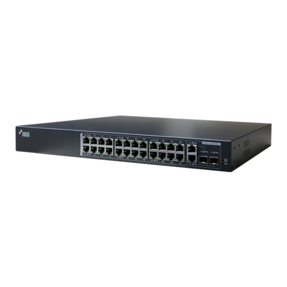
Part 1 - Introduction Accessories Upon unpackaging the product, check the contents inside to ensure that all the following accessories are included. ● DH-2026PF ● Power Cable ● Manual ● Rack Mount Brackets: 2EA ● Screws : 6EA ● Rubber Feet : 4EA Overview Front Panel RJ-45 Service Ports... - Page 11 Part 1 - Introduction 1 RJ-45 Service Ports These are PoE-enabled RJ-45 ports. Connect a network camera to one of these ports. • PoE-supported network cameras will receive power over the signal line, without the use of an external power source. • Each port is enabled with Auto-MDI/MDI-X detection and operates as a 10/100Mbps full/half duplex mode.
- Page 12 Part 1 - Introduction LED Status Indications Mode Status Color Description Amber Normal network connection at 10/100Mbps Data transmission over the network in progress at Blinking Amber 10/100Mbps Off for (Link/Activity) more than Amber The port is in a loopback state, and the connection is blocked 10 seconds after On No network connection or a problem with the connection...
- Page 13 Part 1 - Introduction 4 RJ-45 Uplink Combo Port LEDs These LEDs indicate the status of the RJ-45 uplink combo ports. The LED color indicates connection and communications speeds with the connected device. LED Status Indications Mode Status Color Description Amber Normal network connection at 10/100/1000Mbps Data transmission over the network in progress at...
- Page 14 Part 1 - Introduction Uplink combo port operation priority information For both the SFP combo port and the RJ-45 combo port are connected to one combo port, the SFP combo port will behave with priority over the RJ-45 combo port regardless of the order of the connection.
- Page 15 Part 1 - Introduction 6 SFP Uplink Port These SFP uplink combo ports are used to connect the switch to higher tier devices. These ports are useful when cascading multiple network devices. • If not using for uplinking purposes, these ports can be used as service ports but they do not support PoE.
-
Page 16: Rear Panel
Part 1 - Introduction Rear Panel Power Connector Vent 1 Power Connector Connect the power cable to this connector. This product does not feature a separate power on/off button and will turn on the moment power is supplied. • Organize the power cable so that it will not cause people to trip over or become damaged from chairs, cabinets, desks, and other objects in the vicinity. -
Page 17: Part 2 - Installation
Part 2 - Installation Tools for Installation Check the following accessories. You will need more tools beside the accessories which are not provided. ● DH-2026PF ● Power Cable ● Manual Tools for mounting to a rack ● Rack Mount Brackets: 2EA, Screws: 6EA ●... -
Page 18: Installation
Part 2 - Installation Installation Place the product in a even and safe place, and prepare for a regular headed screwdriver of medium size ( 0.6 cm). Using a cross screwdriver, attach the bracket to both corners of the product, as shown in the first illustration below (how to install the bracket on the product). -
Page 19: Port Connection
Part 2 - Installation Port Connection DirectIP™ NVR Connection Via UTP Cable Connect the DirectIP™ NVR's VIDEO IN/Ext. port to the system's RJ-45 uplink combo port using a UTP cable. Check the RJ-45 uplink combo port SPD LED's status and verify that a normal connection has been established. - Page 20 Part 2 - Installation Remote Connection via an Optical Cable Insert an SFP module into the DirectIP NVR or Switch's SFP port and connect one end of the optical cable to the module. Insert an SFP module into the system's SFP uplink port and connect the other end of the optical cable to the module.
-
Page 21: Directip™ Camera Connection
Part 2 - Installation DirectIP™ Camera Connection Connect the system's RJ-45 service port to the network camera's RJ-45 port using a UTP cable. Check the RJ-45 service port LED's status and verify that a normal connection has been established. PoE cameras connected to RJ-45 service ports can receive power through the UTP cable. -
Page 22: Cascading
Cascading Connect the RJ-45 uplink combo ports of system 1 and system 2 using a UTP cable. Check the RJ-45 uplink port SPD LED's status and verify that a normal connection has been established between the two products. If the PoE switch is not connected to network connection at 1000Mbps, the network bandwidth may not be enough, and the NVR may not record video normally. - Page 23 Remote Connection via an Optical Cable Insert SFP modules into the SFP uplink combo ports of system 1 and system 2 and then connect the modules using a fiber optic cable. Check the SFP uplink combo port LEDs and verify that a normal connection has been established.
-
Page 24: Port Connection Warnings And Tips
Port Connection Warnings and Tips Keep the UTP cable length to less than 100m. • Only use category 5 or higher UTP cables with RJ-45 connectors to connect to the system. The system's ports can automatically distinguish between MID and MDIX connectors, so there is no need to use a crossover cable when connecting to a different device's RJ-45 port. -
Page 25: Part 3 - Miscellaneous
Part 3 - Miscellaneous Supported SFP Transceiver Module List The system's SFP ports support the following types of SFP modules: Diameter Wavelength Standard Length Mode Connector SFP Module (um) (nm) 50/125 500m Multi Finisar 1000BASE-SX FTL8519P3BNL 62.5/125 300m Multi Finisar 1000BASE-LX 9/125 1310... -
Page 26: Troubleshooting
Part 3 - Miscellaneous Troubleshooting Problem Check ● Check the power cable. Power LED will not turn on. ● Check the power supply status to the outlet the power cable is connected to. The system shuts down shortly after Check power connection components for electric powering on. -
Page 27: Specifications
Part 3 - Miscellaneous Specifications Model DH-2026PF Embedded CPU System Memory 32MB SDRAM, 16M Flash Switching Capacity 8.8Gbps 24 RJ-45 Connectors Copper Service Port (10/100BASE-T) Copper Uplink Combo Port 2 RJ-45 Combo Connectors (10/100/1000BASE-T) SFP Uplink Combo Port 2 SFP Connectors (1000BASE-X) Rated input AC 100-240V, 50/60Hz Power Consumption... - Page 28 IDIS Co., Ltd. For more information, please visit at www.idisglobal.com...