
Related Manuals for Ascension 5442P


Summary of Contents for Ascension 5442P
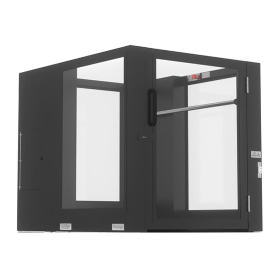
- Page 1 ASCENSION PROTEGE PORTABLE WHEELCHAIR LIFT MODEL 5442P MAINTENANCE & REPAIR MANUAL Patented – see www.ascension-lift.com/patents...
- Page 3 ASCENSION PROTEGE PORTABLE WHEELCHAIR LIFT MODEL 5442P MAINTENANCE & REPAIR MANUAL...
- Page 4 Copyright © 2018 Ascension, a Division of AGM, Tucson, Arizona This document, or parts thereof, may not be reproduced in any form, by any method, for any purpose, without written the permission of Ascension.
-
Page 5: Table Of Contents
TABLE OF CONTENTS INTRODUCTION ......................1 About This Manual ..................... 1 Additional Information ....................2 Getting Help ....................... 2 Contacting Ascension ....................2 SECTION 1 Terminology ....................3 SECTION 2 Routine Maintenance ................. 5 Hydraulic System .................... 5 Cleaning ......................5 SECTION 3 Mechanical Disassembly and Repair ............ - Page 6 Testing the Smart Relay ................34 Testing the Power Supply ................35 Testing the Power Relay ................35 SECTION 5 Lift Compression/Expansion ..............37 Compressing the Lift ..................38 Expanding the Lift ..................42 Verification of Operation ................45 SECTION 6 Troubleshooting ..................46...
-
Page 7: Introduction
INTRODUCTION The purpose of this manual is to provide the necessary information to perform maintenance and repairs on the Ascension PROTEGE portable wheelchair lift. This manual is intended to be used by skilled technicians who have experience working on electro-mechanical systems and devices. Furthermore, these personnel should be well- versed in standard industrial safety practices and procedures. -
Page 8: Additional Information
Also, it is recommended that you contact Ascension while in the immediate vicinity of your lift, as this will reduce the time required to properly diagnose the problem. -
Page 9: Section 1 Terminology
Maintenance & Repair Manual SECTION 2 PROTEGE 5442P SECTION 1 Terminology To effectively use this manual, you need to be familiar with the following terms. Refer to the figure on the following page for identification of components. Not all components are shown in the figure. - Page 10 Maintenance & Repair Manual SECTION 2 PROTEGE 5442P 112510 REV H...
-
Page 11: Section 2 Routine Maintenance
Maintenance & Repair Manual SECTION 2 PROTEGE 5442P SECTION 2 Routine Maintenance Hydraulic System The fluid level of the hydraulic system should be checked every six months. Before checking the fluid level, make sure the platform is at ground level (i.e., at the lower landing) and off its casters. -
Page 12: Section 3 Mechanical Disassembly And Repair
Maintenance & Repair Manual SECTION 3 PROTEGE 5442P SECTION 3 Mechanical Disassembly and Repair Important Preliminary Information The repairs in this section are to be performed by a skilled technician who has experience working on electro-mechanical systems. Furthermore, the technician should be well-versed in standard industrial safety practices and procedures. -
Page 13: Removing The Sheet Metal Skins
Maintenance & Repair Manual SECTION 3 PROTEGE 5442P Removing the Sheet Metal Skins For some of the repairs described in this manual, it is necessary to gain access to the inner components of the lift beyond what is possible with the sheet metal "skins" still on the lift. -
Page 14: Operating Stations
Maintenance & Repair Manual SECTION 3 PROTEGE 5442P Operating Stations The operating stations house the UP/DOWN rocker switches and, on the station inside the platform, the emergency stop button. To test or remove either of these switches, use a Phillips screwdriver to remove the two (2) screws that secure the switch plate to the platform and pull the plate away from the platform. -
Page 15: On/Off Switch
Maintenance & Repair Manual SECTION 3 PROTEGE 5442P On/Off Switch The On/Off rocker switch may be set to ‘OFF’ to prevent operation of the lift at the owner’s discretion. The lift will only operate when the switch is set to ‘ON.’... - Page 16 Maintenance & Repair Manual SECTION 3 PROTEGE 5442P The optical beam must always pass through the area marked with the yellow decal, shown in the figure above. The following procedure can be used if the optical sensor is misaligned: 1. Remove the outer left sheet metal skin to gain access to the height sensor.
-
Page 17: Lower Terminal Switch
Maintenance & Repair Manual SECTION 3 PROTEGE 5442P Lower Terminal Switch The lower terminal switch notifies the controller that the platform has reached ground level. It is actuated by the right vertical guide rail when the platform is less than 0.5 inches [13 mm] above the ground, which allows for the front gate to be opened and makes sure the lift stops properly when it reaches the ground. -
Page 18: Upper Platform Gate Switch
Maintenance & Repair Manual SECTION 3 PROTEGE 5442P Upper Platform Gate Switch The upper platform gate switch detects whether the upper platform gate is open or closed. The switch is only visible with the machinery cabinet sheet metal skin on the handle side of the gate removed, and is located on the lift frame about 26"... -
Page 19: Front Gate Interlock Switch
Maintenance & Repair Manual SECTION 3 PROTEGE 5442P Front Gate Interlock Switch The front (lower landing) gate is equipped with an interlock switch performs two functions: first, it prevents the lift from operating unless the gate is closed and locked, and second, it prevents the gate from being opened while the lift is in use. - Page 20 Maintenance & Repair Manual SECTION 3 PROTEGE 5442P To remove the interlock switch, perform the following steps: 1. Remove the front and rear sheet metal covers on the strike side of the gate. 2. Disconnect the Molex connector that is wired to the interlock switch.
-
Page 21: Tilt Sensor
Maintenance & Repair Manual SECTION 3 PROTEGE 5442P 3.10 Tilt Sensor The tilt sensor is located at the bottom of the right-hand machine cabinet, below the hydraulic power unit. The tilt sensor is set to allow operation on level ground, but disable operation when the lift is set on an incline greater than 5%. -
Page 22: Hydraulic Valves
Maintenance & Repair Manual SECTION 3 PROTEGE 5442P 3.11 Hydraulic Valves The hydraulic valves are located inside the right-hand machinery cabinet. It may be necessary to remove the machinery cabinet skins per Section 3.3 to access some of the valves. - Page 23 Maintenance & Repair Manual SECTION 3 PROTEGE 5442P the counterbalance valve is malfunctioning and must be replaced (with the platform at the lower landing). Before removing this valve, pull the electrical harness connectors off of the coil terminals. Then remove the black button by turning it counterclockwise, and pull the coil off the valve.
-
Page 24: Windows
Maintenance & Repair Manual SECTION 3 PROTEGE 5442P 3.12 Windows The windows on the lift are pinched in the channel of a glazing strip which is attached to the lift frame with screws. See the figure below. To remove a window, remove each of the screws attaching the four glazing strips to the lift’s exterior. -
Page 25: Platform Floor Removal
Maintenance & Repair Manual SECTION 3 PROTEGE 5442P 3.13 Platform Floor Removal WARNING! Use caution when removing the platform floor, as it is large and weighs approximately 80 pounds. It is recommended that two (2) people remove the floor. The platform floor must be removed in order to compress the lift to move it through a narrow doorway. - Page 26 Maintenance & Repair Manual SECTION 3 PROTEGE 5442P To reinstall the floor, perform the above steps in reverse order. If the platform floor is being reinstalled for the expansion procedure, instead refer to Section 5.2. 112510 REV H...
-
Page 27: Lower Gate Closer Adjustment
Maintenance & Repair Manual SECTION 3 PROTEGE 5442P 3.14 Lower Gate Closer Adjustment The lower gate is closed by a spring closer with hydraulic damping to control closing speed. When the lower gate closer is properly adjusted, the gate will close in approximately five (5) seconds. - Page 28 Maintenance & Repair Manual SECTION 3 PROTEGE 5442P 5. Pull the closer arm until it is fully extended and then allow it to retract fully. In order for the gate to close in five (5) seconds as desired, the closer rod should take approximately seven (7) seconds to fully retract when not attached to the gate.
-
Page 29: Upper Gate Closer Adjustment
Maintenance & Repair Manual SECTION 3 PROTEGE 5442P 3.15 Upper Gate Closer Adjustment The upper gate has two (2) closers: a hydraulic closer and a chain closer. The upper gate will close in approximately five (5) seconds if the closers are functioning properly. - Page 30 Maintenance & Repair Manual SECTION 3 PROTEGE 5442P It is not recommended to adjust the chain closer. To remove the chain closer, perform the following procedure: 1. Open the upper platform gate approximately halfway and use the hold-open washer on the hydraulic closer to hold the gate open.
-
Page 31: Safety Pan Switches
Maintenance & Repair Manual SECTION 3 PROTEGE 5442P 3.16 Safety Pan Switches The safety pan assembly is in place to make sure that the area under the platform is clear of obstructions while the platform is descending. The safety pan consists of four main components: the front safety pan, the rear safety pan, and two safety pan bridges. - Page 32 Maintenance & Repair Manual SECTION 3 PROTEGE 5442P switch, disconnect the switch from the safety pan harness and remove the mounting screw holding the safety pan to the bracket (see Section 3.17). Then use a Phillips screwdriver to remove the two (2) pan head screws holding the bracket to the frame.
-
Page 33: Safety Pan Removal
Maintenance & Repair Manual SECTION 3 PROTEGE 5442P 3.17 Safety Pan Removal The safety pan assembly must be removed to compress the lift and move it through a narrow doorway. To remove the safety pan, perform the following procedure: 1. Make sure the platform is at ground level and the lift is resting securely on its base (not on its casters). - Page 34 Maintenance & Repair Manual SECTION 3 PROTEGE 5442P 4. Using a Phillips screwdriver, remove the four (4) small screws from each of the two (2) safety pan bridges and lift the rear safety pan out from under the lift. Set the rear safety pan, two (2) bridges, and eight (8) screws aside.
-
Page 35: Section 4 Electrical Testing
Maintenance & Repair Manual SECTION 4 PROTEGE 5442P SECTION 4 Electrical Testing This section contains information that will enable a skilled and experienced electrician to service the lift. The electrical and logic diagrams for the lift are shown on the following pages. - Page 36 Maintenance & Repair Manual SECTION 4 PROTEGE 5442P Figure 1 electrical diagram 112510 REV H...
- Page 37 Maintenance & Repair Manual SECTION 4 PROTEGE 5442P Figure 2 relay logic RELAY MODULE LOGIC Notes: The logic diagram above does not include any of the timers or more complicated components of the logic circuit. Rather, it only shows the contacts that must be maintained for the platform to run up or down.
-
Page 38: Access To The Electrical Panel
Maintenance & Repair Manual SECTION 4 PROTEGE 5442P Access to the Electrical Panel The electrical panel can be accessed by removing the right sheet metal cap. Refer to Section 3.3. Refer to the figure below for identification of the major components on the electrical panel. -
Page 39: Testing The Switches
Maintenance & Repair Manual SECTION 4 PROTEGE 5442P Testing the Switches Each of the lift's switches can be tested by locating the switch, removing the switch from the lift if necessary, and checking for continuity across the contacts on the back of the switch. -
Page 40: Testing The Smart Relay
4. The power supply is not supplying 24 VDC. Refer to Section 4.4 to check it. 5. There has been a wiring harness or connector failure. See the Electrical Diagram on page 30 to continue troubleshooting, or contact Ascension. 112510 REV H... -
Page 41: Testing The Power Supply
Maintenance & Repair Manual SECTION 4 PROTEGE 5442P Testing the Power Supply The power supply is located on the control panel. See Section 4.1. The AC power must be on to conduct the following tests. If the green LED is illuminated, the unit is supplying 24 VDC. If the LED is not illuminated, check to see that the AC supply is on. - Page 42 Maintenance & Repair Manual SECTION 4 PROTEGE 5442P relay contacts indicated in Step 1 above while jumping from the "L+" contact on the smart relay to the "14" contact on the power relay. If the voltage drop does not go to approximately 0 VAC, then the power relay is not functioning correctly and needs to be replaced.
-
Page 43: Section 5 Lift Compression/Expansion
This section describes the procedures for compressing the lift and then expanding it again. A toolkit is available for purchase from Ascension that contains several of the tools required for the process; however, the owning facility may use its own tools in place of the kit if desired. -
Page 44: Compressing The Lift
Maintenance & Repair Manual SECTION 5 PROTEGE 5442P Compressing the Lift To compress the lift, complete the following steps in the order listed. CAUTION! Take care when placing any part of your body under the platform. CAUTION! Wear safety glasses at all times while performing the following procedures. - Page 45 Maintenance & Repair Manual SECTION 5 PROTEGE 5442P 6. Loosen the eight (8) platform cross-member bolts and six (6) base cross-members with a 9/16" open-end wrench until the bolts can be comfortably turned by hand (approximately 0.5" [13 mm] of thread should be visible).
- Page 46 Maintenance & Repair Manual SECTION 5 PROTEGE 5442P Figure 4 strap compression 8. Use the ratcheting strap to compress the lift to the desired width. During this process, it may be necessary for a second person to assist by pushing the lift base inward from either side.
- Page 47 Maintenance & Repair Manual SECTION 5 PROTEGE 5442P Ratchet buckle instructions for the strap supplied with the Ascension Toolkit 112510 REV H...
-
Page 48: Expanding The Lift
Maintenance & Repair Manual SECTION 5 PROTEGE 5442P Expanding the Lift To expand the lift from its compressed state, complete the following steps in the order listed. CAUTION! Take care when placing any part of your body under the platform. - Page 49 (the 6" long 1/8" hex key provided in the Ascension Toolkit is recommended, but any long hex key will suffice). It also may be required to press the "Down"...
- Page 50 Maintenance & Repair Manual SECTION 5 PROTEGE 5442P 11. Reattach the safety pan assembly. Refer to Section 3.17 for instructions. 12. Close and lock all four (4) access panels, if open. WARNING! Verify the correct operation of the lift, as described in Section 5.3, before using the lift.
-
Page 51: Verification Of Operation
If any of the above conditions is not met, and the problem cannot be corrected by reviewing or repeating the reassembly steps, remove the lift from service and contact Ascension immediately. 112510 REV H... -
Page 52: Section 6 Troubleshooting
Maintenance & Repair Manual SECTION 6 PROTEGE 5442P SECTION 6 Troubleshooting The table below presents the necessary information to perform basic troubleshooting on the lift. The numbers in the Section column refer to sections within this manual. For the sake of completeness, many of the items in this table are of a setup and operational nature and are not specifically addressed in this manual. - Page 53 Maintenance & Repair Manual SECTION 6 PROTEGE 5442P Problem Possible Cause Remedy Section suddenly Upper height stop reflector is Set the upper height stop positioned incorrectly reflector properly per the Operating Manual Platform does Upper height stop reflector is Set the upper height stop...
- Page 54 Maintenance & Repair Manual PROTEGE 5442P Notes: 112510 REV H...
- Page 56 A DIVISION OF AGM Printed in the U.S.A. MAINTENANCE & REPAIR MANUAL 112510 REV H...
Need help?
Do you have a question about the 5442P and is the answer not in the manual?
Questions and answers