Advertisement
C3-4 60 Installation and Connection Guide
1.
Cautions
Please pay attention to the following items. Mis-operation may lead to
1) Do not power on the system before the installation is completed. Do not carry on the install or repair operation at power on state.
2) All external devices must be grounded.
3) It is recommended that all wires should run through PVC or galvanized pipes.
4 We recommend that the exposed part of all wires should be shorter than 4 mm, t
)
caused by unexpected contact of exposed wires.
5) It is recommended that the card reader and exit button should be installed at height about 1.4-1.5m.
6) It is recommended to use the separated power supply for the control panel and the lock.
Description of normal working state:
Power on the system . In normal working state, the power (red) and run indicator (yellow) is on constantly, and the communication
indicator (green) flashes.
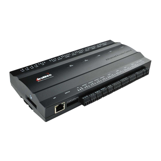
2.
Components
State Indicator
Box Lock Hole
Heat
Dissipation Hole
Thread Hole
Appearance of Panel Box
3.
Installation
After the following installation, fix the panel on the track first, and then install other components to original positions.
Thread holes
1) Get through the thread hole
Version:1 . 0 Date: Mar. 2011
equipment failure even the
personal injury.
o avoid short circuit or communication failure
Control Panel
Backup Battery
Temper Switch
Air Switch
Panel Track
Power Supply
Get the Panel off the track
Internal of Panel Box
Screws
Control Panel
Panel Track
2) Fix the box
3) Install other components
4.
LED Indicators and Wire Illustration
Notes:
1) Meaning of LED indicators:
LINK indicator (green): Light always indicates TCP/IP communication
is proper;
ACT indicator (yellow): Flash state indicates the data is in transmitting
through TCP/IP communication.
EXT RS485 indicator (yellow&green): Flash state indicates it is sending
or receiving data through RS485 communication.
PC RS485 indicator (yellow&green): Flash state indicates it is sending
or receiving data through RS485 communication.
POWER indicator (red): Light always indicates the control panel is
power on.
RUN indicator (green): Flash state indicates the system works normally.
CARD indicator (yellow): Flash state indicates card is punched on reader.
LINK
Ethernet interface
ACT
Dip switch
PC RS485 interface
D
Auxiliary output1
Control Panel
D
Auxiliary output2
1
D
Auxiliary output3
2
D
Auxiliary output4
C
#1 Door
C
#2 Door
C
#3 Door
C
#4 Door
1
A
2
Lock Power
A
Power of Control Panel
2) Recommended use of wires:
A. Use 2-conducotor power cord.
B. Use 6-conductor wire between Wiegand reader and control panel
(RVVP 6*0.5mm) (To choose the proper cord according to the
interface you connect, such as 6, 8, 10 cord.)
C. Use 4-conducotor lock power cord (RVV 4*0.75mm)
D. Use 2-conducotor switch power cord (RVV 2*0.5mm)
3) The auxiliary input may be connected to infrared body detectors,
alarm switches, etc.
4 The auxiliary output may be connected to door bells, alarms, etc.
)
5) State Indicator is connected to the panel box, that is power indicator,
run status indicator and communication status indicator.
{
{
{
{
{
{
{
{
{
{
{
Auxiliary Input1
D
Auxiliary Input2
D
Auxiliary Input3
D
Auxiliary Input4
D
EXT RS485
PWR
State Indicator
#1 Door
Exit Button
D
#1 Door
Wiegand reader
B
#2 Door
D
Exit Button
#2 Door
B
Wiegand reader
#3 Door
D
Exit Button
#3 Door
B
Wiegand reader
#4 Door
D
Exit Button
#4 Door
B
Wiegand reader
Advertisement
Table of Contents

Related Manuals for Zksoftware C3-460

Summary of Contents for Zksoftware C3-460
- Page 1 LED Indicators and Wire Illustration C3-4 60 Installation and Connection Guide Notes: 1) Meaning of LED indicators: 2) Recommended use of wires: Version:1 . 0 Date: Mar. 2011 A. Use 2-conducotor power cord. LINK indicator (green): Light always indicates TCP/IP communication is proper;...
- Page 2 . DIP Switch Settings Equipment Communication 1) Number1-6 switch are used to set the control panel number in RS485 communication: It is adopted binary coding and little endian, the address The PC software can communicate with the panel according to the communication protocols (RS485 and TCP/IP) for data exchange and number setting by place these 6 switches are shown as figure below.
Need help?
Do you have a question about the C3-460 and is the answer not in the manual?
Questions and answers