
Related Manuals for Basler MVC 236


Summary of Contents for Basler MVC 236
- Page 1 ELECTRONIC MANUAL VOLTAGE CONTROL MODULE Model: MVC 236 Part Number: 9 2043 00 100 Publication Number: 9 2043 00 990 Revision: G 7/99...
- Page 2 CONFIDENTIAL INFORMATION of Basler Electric Company, Highland, IL. It is loaned for confidential use. Subject to return on request and with the mutual understanding that it will not be used in any manner detrimental to the interests of Basler Electric Company.
-
Page 3: Table Of Contents
MVC 236 Block Diagram ..............2-1 MVC 236 Outline Drawing..............3-1 Manual Voltage Adjust Rheostat ............3-2 Spike Suppression Module Outline Drawing ........3-2 Typical MVC 236 Interconnection ............3-4 MVC 236 Interconnection with Nullmeter Circuit........3-5 MVC 236 Operational Test..............4-2 Troubleshooting..................5-2 List of Tables Table... -
Page 4: Section 1 General Information
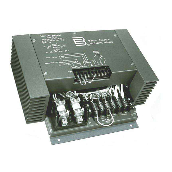
1-2. GENERAL DESCRIPTION The MVC 236 is a solid-state device enclosed in a metallic, dark gray chassis and is designed for behind-the-panel mounting. Two terminals strips located on the front of the unit facilitates installa- tion and operation. -
Page 5: Spike Suppresson Module
MVC 236 Voltage Regulator. In these cases, Basler Electric recommends the use of the Spike Suppression Module which was supplied with the Regulator to filter out these potentially... -
Page 6: Section 2 Principles Of Operation
The MVC 236 is designed to operate from 60, 120, or 240 Vac nominal sources by making a simple tap change. Taps are also provided to select 32, 63, or 125 Vdc outputs. A jumper is used to select the proper input power frequency. -
Page 7: Section 3 Installation Instructions
INSTALLATION INSTRUCTIONS 3-1. MOUNTING a. Manual Voltage Control Module Mounting. The MVC 236 must be mounted vertically for maximum cooling. The unit can be mounted anywhere that the ambient temperature does not exceed the environmental conditions (refer to Table 1-2). -
Page 8: Spike Suppression Module Mounting
Figure 3-2. Manual Voltage Adjust Rheostat. b. Spike Suppression Module Mounting. The Spike Suppression Module will operate when mounted in any position. The Spike Suppression Module can be mounted in any location where the ambient temperature does not exceed the operational limits. Due to its rugged construction, the Spike Suppression Module can be mounted directly on the generator. -
Page 9: Interconnection
Incorrect use of such equipment could damage com- ponents contained in the device. a. General. The MVC 236 connects with the generator system as shown in Figures 3-4 and 3-5. Number 14 gauge wire or larger should be used for connections to the unit. -
Page 10: Typical Mvc 236 Interconnection
Figure 3-4. Typical MVC 236 Interconnection. -
Page 11: Mvc 236 Interconnection With Nullmeter Circuit
Figure 3-5. MVC 236 Interconnection with Nullmeter Circuit. -
Page 12: Operation
Figure 4-1 for a bench test. Notice that an automatic voltage regulator is not required for this test. a. With all power removed from the MVC 236, connect the unit into the test circuit as shown by Figure 4-1. -
Page 13: Mvc 236 Operational Test
Figure 4-1. MVC 236 Operational Test. Connect the FIELD VOLTAGE JUMPER for 63 Vdc. g. Apply power and slowly rotate the MANUAL VOLTAGE ADJUST control clockwise (CW) and observe that the brightness of the light bulb increases proportionally until reaching full brightness. -
Page 14: Section 5 Maintenance And Troubleshooting
SECTION 5 MAINTENANCE AND TROUBLESHOOTING 5-1. PREVENTIVE MAINTENANCE A periodic inspection of the MVC 236 should be made to ensure that it is clean and free from accumulations of dust and moisture. Verify that all terminal connections are clean, free of corrosion, and tight. - Page 15 Figure 5-1. Troubleshooting.
Need help?
Do you have a question about the MVC 236 and is the answer not in the manual?
Questions and answers