
Related Manuals for Basler MVC 300


Summary of Contents for Basler MVC 300
- Page 1 ELECTRONIC MANUAL VOLTAGE CONTROL Model: MVC 300 Part Number: 9 1210 00 106 Publication Number: 9 1210 00 993 Date: July, 1993 Revision F: July, 1996...
-
Page 2: Confidential Information
CONFIDENTIAL INFORMATION of Basler Electric Company, Highland, IL. It is loaned for confidential use. Subject to return on request and with the mutual understanding that it will not be used in any manner detrimental to the interests of Basler Electric Company. -
Page 4: General Information
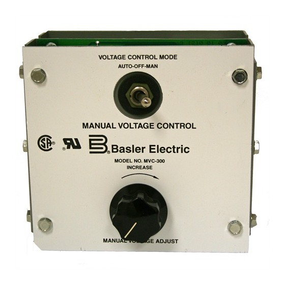
VOLTAGE ADJUST control and an AUTO-OFF-MANUAL voltage control mode switch are provided on the front panel. 1-3. SPECIFICATIONS Table 1-1 provides the electrical and physical specifications of the MVC 300. Table 1-1. Specifications. Input Power: 120 Vac, + 10%Single-Phase, 50-320 Hz. -
Page 5: Principles Of Operation
SECTION 2 PRINCIPLES OF OPERATION 2-1. GENERAL a. The Electronic Manual Voltage Control (MVC-300) is a phase-controlled, silicon-controlled, rectifier (SCR) bridge. By adjusting the front panel MANUAL VOLTAGE ADJUST control, the firing angle of the SCR change providing an adjustable voltage level to the exciter field. b. -
Page 6: Installation
MANUAL VOLTAGE ADJUST control can be removed and installed remotely by using terminals 14, 15 and 16 or a Basler motor operated control (MOC 2) with a 10 k ohm control element can be connected to terminal 14, 15, and 16. See Figure 3-3 Interconnection Diagram. It is imperative that the MVC-300 be connected to provide an output which corresponds to the voltage regulator ratings in order to prevent damage to the MVC-300 or the regulator. - Page 7 Figure 3-1. Panel Drilling Template...
- Page 8 Figure 3-2. MVC 300 Outline Drawing.
- Page 9 Figure 3-3. MVC 300 Interconnection Diagram, Typical.
-
Page 10: Operational Test
Table 3-1. Voltage Selection Chart. Voltage Regulator Voltage Regulator MVC Input Voltage Selection Model Rating Voltage Terminal KR7F,KR7FF, 125 V @ 7 A or less 240 Vac SR8A,SR8F SR4A,SR4F, 63 V @ 7 A or less 120 Vac KR4F,KR4FF XR2001,XR2004 63 V @ 7 A or less 240 Vac KR2F,KR2FF... - Page 11 Figure 3-4. Operational Test Set-Up Diagram. (3) With the MANUAL VOLTAGE ADJUST control fully counter-clockwise (CCW) apply a source of 120 Vac to Terminals 23 and 24 of the MVC-300. Slowly rotate the MANUAL VOLTAGE ADJUST control clockwise (CW) and observe that the brightness of the light bulb increases proportionally until it reaches full brightness.
-
Page 12: Maintenance And Troubleshooting
Due to a protective coating, repair/replacement of individual components on the printed circuit board assembly should not be attempted and the complete replacement of the board is recommended. When ordering replacement parts from Basler Electric always specify the part number, the quantity and the description of the item. - Page 13 If the generator output voltage does not build-up, replace the MVC 300. If the generator output voltage builds-up, proceed to Step 6. Step 6. Verify that the generator output can be controlled by the MVC 300 front panel potentio- meter.
Need help?
Do you have a question about the MVC 300 and is the answer not in the manual?
Questions and answers