Table of Contents
Advertisement
Quick Links
Advertisement
Table of Contents

Related Manuals for Licht-Technik Motoryoke YipMan

Summary of Contents for Licht-Technik Motoryoke YipMan
- Page 1 Motoryoke YipMan MB-DY V1 Software version 4.58 Functional description Fabrication and marketing Licht-Technik Vertriebs GmbH Hagenbach & Grill Osterwaldstr. 9-10 80805 München Tel. 089-360528-0 Fax 089-360528-30 Last updated on: 31/07/2020 Rev.: 1.00 Motoryoke YipMan1 V4.58 Rev 1.00...
- Page 2 Caution! Operate the device only after having read and understood operating instructions Please read first the operating and safety instructions on page 6 Motoryoke YipMan1 V4.58 Rev 1.00...
-
Page 3: Table Of Contents
Inhaltsverzeichnis Introduction........................... 4 Appropriate use........................4 The Licht-Technik motoryoke YipMan.................. 4 Safety- and operating instructions..................6 Quick start guide........................9 Assembling the moving device................... 10 Identification........................11 The DMX-standard in lighting..................... 11 Cabling..........................12 Getting started........................14 PAN – axis moving range....................15 User interface........................ -
Page 4: Introduction
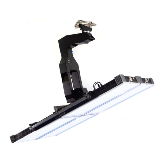
The safety and operating instructions must be observed. The Licht-Technik motoryoke YipMan With the Licht-Technik motoized yoke, we can offer an flexible, versatile, precise, durable and reliable device for positioning of different devices. Company Licht-Technik developes motoryokes since 1991 for film, TV an theatre lighting. - Page 5 Because of the absolute value device, the motoryoke does not perform any initialisation runs after power up. In addition a power down does not affect the current position, also because of the self-locking gearboxes. The lighted LCD display (the light can be switched off) leads the user in plain text instructions through the various programming steps.
-
Page 6: Safety- And Operating Instructions
Safety- and operating instructions Danger to life! Before opening the housing disconnect the device from the mains !!! Do not try in any case to touch the electronic through openings, also with any objects. This can cause an electrical accident that can lead to death! Please note: The switching or rising/falling from one input voltage range to another during operation can lead to damage of the device! When using a generator, first start the generator and wait for stable mains supply... - Page 7 That applies also to the transport. It is absolutely forbidden to hang up the yoke on its spigot when transported! If you want to use a transport carriage, it must be certified by Licht-Technik! The fastening spigot must be checked visual once a year. The spigot must be in right angel to the housing.
- Page 8 Damages and indirect damages or every kind of costs, which result from the use of – Licht-Technik products. Any damages which result from negligence, improper use and setup, wrong setting into – operation and use, ignoring of valid safety regulations, unsuitable use, bad maintenance of Licht-Technik products. Motoryoke YipMan1 V4.58 Rev 1.00...
-
Page 9: Quick Start Guide
Quick start guide Prior starting, observe the safety and operating instructions on page 6!!! Follow the description step by step to mount the lamp and program the yoke! For cable connections, please refer to section cabling, page Assembling position: First, the yoke must move to build-in position. The yoke must hang in a rigg. Connect power cable, but let it switched off. -
Page 10: Assembling The Moving Device
Assembling the moving device Cabling and connecting possibilities are described on page 12 Start with mains in only! Do not connect the DMX line! Power on the motoryoke Use the quick start guide on page 9. When all axles have been moved to loading position, assemble the payload: 1. -
Page 11: Identification
Identification The motoryokes are identified by a number on the identification plate as follows: MB – XX Motoryoke. On every motoryoke identification plate. Type: Studio yoke Type: tube yoke Type: Show yoke Type: Flexible in width Type: One point connection (YipMan) The DMX-standard in lighting Because of many problems with analogue data-signals from the control panels to the dimmers the DMX-standard was developed in 1990. -
Page 12: Cabling
Cabling Caution! Please read the operating and safety instructions on page 6 (continuing) before cabling! Make sure that the motoryoke is switched off before cabling! Caution! Make sure that the cables run in wide loop to the motoryoke. Check, if the cables are long enough for the complete moving range. - Page 13 A maximum of four units can controlled via Vision Control or LT-Pilot! If you use a standard DMX-desk, please observe the DMX-footprint on page 19 If you use the Vision-Control or the LT-Pilot remote control system, please use the following channels and programming values: DMX-addressing and unit assignment: Unit 1 Unit 2...
-
Page 14: Getting Started
Getting started Mount the motoryoke system at the desired place with observing the operating and safety instructions on page 6! Mount the moving device like described in Assembling the device on page 10. Cable the system like described on page 12. Switch on the motoryoke. -
Page 15: Pan - Axis Moving Range
PAN – axis moving range Basically: The PAN-axle is the axle which moves the lamp horizontally. The moving range of the main axles can be adapted individually. For the PAN-axle are two parameters required. The middle position and an angle in which the motoryoke should move. - Page 16 Setting the PAN middle position: The middle position normally is the position in which the installed device is used most. It can be set at menu P05, PAN-axis middle position, page 22. You should start with the pan axis in the current adjusted middle position. If you do not know if this is the case, power up the device and set the DMX-channel for position to 50%.
- Page 17 TILT – axis moving range Basically: The TILT-axle is the axle which moves the lamp vertically. Normally the factory presettings are suitable and nothing must be set. The lamp can be moved from vertically down to a few degrees on the top. The 0-degree position represents the vertical position of the mounting socket.
-
Page 18: User Interface
MENU key In normal operating mode the LCD-display indicates different information. The first line shows the Licht-Technik moving text with details on type of device, software version and telephone number. The second line indicates the first DMX-address and its incoming value (8-Bit, 0..255). -
Page 19: Dmx Channels Motoryoke
DMX channels motoryoke The following chapters require the DMX-channel assignment of the motoryoke. Please note the difference which is programmed in P27, PAN/TILT DMX speed channel setup, page 29. This menu determines if the speed is given by one or by two channels. Therefore, the motoryoke requires between 5 (without optional components) and 12 DMX- channels. -
Page 20: P01 Dmx-Address Motoryoke
P01 DMX-Address motoryoke At this point the first DMX-address of the motoryoke can be adapted to the desired DMX- address of the light mixing panel. This address represents the PAN-DMX-address. All other addresses follow this address. Refer to DMX-channels motoryoke, page 19 Range of values: Address 1..512 Operation: Menü... -
Page 21: P02 Rotation Unit On/Off
P02 Rotation unit ON/OFF At this point an optional rotation module can be switched ON or OFF. The speed of the rotation axle is fixed, so no speed channel has to be set. See DMX channels motoryoke, page 19. If no rotation unit is used, set this value to 0. Range of values: 0: No rotation module installed Rotation module installed... -
Page 22: P05 Pan-Axis Middle Position
P05 PAN-axis middle position With this function the PAN-axis middle position can be set. Please read first chapter PAN-axis moving range, page 15. Range of values: 2000..2100 unit (value of the absolute value device) Recommended value: 2048. So that the spigots stay the same way as the yoke Operation: Menü... -
Page 23: P06 Tilt-Axis 0-Degree Position
P06 TILT-axis 0-degree position With this function the TILT-axis fine adjustment of the 0-position can be made. Please read first chapter TILT-axis moving range, page 17. This function can only be used for fine adjustment. The TILT axis is not symetrical. It can not be determined which DMX value correspondes to this position. -
Page 24: P11 Pan-Axis Moving Range
P11 PAN-axis moving range At this point the PAN-axis moving range can be programmed. The moving range has as reference point the PAN-axis middle position which can be set in P05, PAN-axis middle position, page 22. For example: If this menu is programmed to 90°, the motoryoke moves 90°... -
Page 25: P12 Tilt-Down (Negative) Moving Range
P12 TILT-down (negative) moving range At this point the TILT-down moving range can be set. For the TILT-axis the moving ranges (up and down) must be programmed individually. The negative moving range is defined as the „direction bottom“ range. The moving ranges have the 0-position as reference point. -
Page 26: P13 Tilt-Up (Positive) Moving Range
P13 TILT-up (positive) moving range At this point the TILT-up moving range can be set. For the TILT-axis the moving ranges (up and down) must be programmed individually. The positive moving range is defined as the „direction top“ range. The moving ranges have the 0-position as reference point. This point can be set in P06, TILT-axis 0-position, page 23. -
Page 27: P14 Focus / Rotation 0%-Value
P14 Focus / rotation 0%-value At this point the position of the focus or the rotation unit for 0% DMX-value can be set. This function is only available, when focus/rotation module is switched on. This can be done in menu P02, rotation module ON/OFF, page 21. Caution! The 0%-value must be smaller than the the 100%-value! (P14 smaller than P15) You have the possibility to set this value automatically. -
Page 28: P15 Focus/Rotation Unit 100%-Value Adjustment
P15 Focus/rotation unit 100%-value adjustment At this point the position of the focus or rotation unit for 100% DMX-value can be set. This function is only available, when focus module is switched on. This can be done in menu P02, Focus module ON/OFF, page 21. Caution! The 100%-value must be greater than the 0%-value! (P15 greater than P14) You have the possibility to set this value automatically. -
Page 29: P27 Speed Pan/Tilt Setup
At this point the number of speed channels can be set. The speed for PAN and TILT axis can be programmed to one channel for both axis or to two channels. One for each axis. When using the Licht-Technik control panels with Joystick, vision conrtrol or LT-Pliot this Parameter must be set to 1. -
Page 30: P30 Displaying The Dmx-Value
P30 Displaying the DMX-value This function assists you in checking the values transmitted by the light mixer panel. At this point you can quickly detect whether the motoryoke is triggered with the correct values. It is possible to check all 512 DMX channels. Note that the value of the address programmed in this menu will be indicated in normal operation. -
Page 31: P32 Selecting The User Language
P32 Selecting the user language At this point you can choose in which language the texts and messages should be displayed. Range of values: 0 = German 1 = English Operation: Menü depress You are now on menu level. The last adjusted menu point is displayed, e.g.: Menu P01: DMX address motoryoke depress ... -
Page 32: P33 Pan-Axis Loading Position
P33 PAN-axis loading position At this point, the PAN axis loading position can be adjusted. It is the position for mounting or dismounting the load. It is very important for mounting or dismounting have the motoryoke on the right position. Otherwise it is not possible to assemble the load. -
Page 33: P34 Tilt-Axis Loading Position
P34 TILT-axis loading position At this point, the TILT axis loading position can be adjusted. It is the position for mounting or dismounting the load. It is very important for mounting or dismounting have the motoryoke on the right position. Otherwise it is not possible to assemble the load. -
Page 34: P35 Rotation-Axis Loading Position
P35 rotation-axis loading position At this point, the rotation axis loading position can be adjusted. It is the position for mounting or dismounting the load. It is very important for mounting or dismounting have the motoryoke on the right position. Otherwise it is not possible to assemble the load. -
Page 35: P36 Interchanging Pan Moving Direction
P36 Interchanging PAN moving direction With this function the PAN moving direction can be set. Range of values: 0 = normal (standard) 1 = reverse direction Recommended value: Operation: Menü depress You are now on menu level. The last adjusted menu point is displayed, e.g.: Menu P01: DMX address motoryoke depress ... -
Page 36: P37 Interchanging Tilt Moving Direction
P37 Interchanging TILT moving direction With this function the TILT moving direction can be set. Range of values: 0 = normal (standard) 1 = reverse direction Recommended value: Operation: Menü depress You are now on menu level. The last adjusted menu point is displayed, e.g.: Menu P01: DMX address motoryoke depress ... -
Page 37: P38 Interchanging Rotation Moving Direction
P38 Interchanging rotation moving direction With this function the rotation moving direction can be set. Range of values: 0 = normal (standard) 1 = reverse direction Recommended value: Operation: Menü depress You are now on menu level. The last adjusted menu point is displayed, e.g.: Menu P01: DMX address motoryoke depress ... -
Page 38: Technical Data
Technical data Weight and dimensions motoryoke: Weight: 41,5kg Maximum payload: 120kg Total weight: 161,5kg Width: 42cm Height: 1,40m Depth: 69cm Mains in: 100 – 240V AC, 47 – 63 Hz, max 2A. Pan moving range (max): 320° Tilt moving range (max): 110°... -
Page 39: Werkseinstellungen
Werkseinstellungen Menu Description Value DMX-Address motoryoke Rotation ON/OFF 1 (ON) PAN-axis middle position Individual TILT-axis 0-degree position Individual PAN-axis moving range 160 degree TILT-axis minus moving range 90 degree TILT-axis plus moving range 10 degree Rotation 0% Ppsition Individual Rotation 100% position Individual Speed PAN/TILT together or separated 1 (separated) -
Page 40: Maintenance
If the spigot is visibly damaged or deformed the motoryoke must not be used anymore. The device has to be sent to Licht-Technik. 2. Checking the safety elements Check the safetybelts and further safetyelements like shackles, rings, lugs, chains: Are the belts not frayed out? –... - Page 41 3. Checking the cables and supply lines Check the cables visibly for damages. – Check the entire moving range of PAN and TILT, if the cables are not broken, bended, – stretched or damaged anyhow. Are the cables not porous? –...
-
Page 42: Error Messages
Error messages Only Licht-Technik trained personal is authorised to work on the motoryoke! Error Description Possible reasons Possible solutions E20 DMX-Signal missing Defective supply line (data power) to the Check the DMX-signal cables. motoryoke. (Pin2 and/or 3 broken) The LED „DMX ok“ at the... -
Page 43: Malfunctions
Malfunctions - No display after power up. The device houses a slow-blow fuse for feeble currents of 6.30 A protecting the equipment of wrong polarities on the supply line. When the fuse is blown, cable and polarity have absolutely be checked (pin1 = 0 V, pin 4 = +24V). - No error message but motoryoke does not move Check DMX-addressing (P01, DMX-Address motoryoke, page 20). -
Page 44: Warranty
All maintenance and servicing works related to the product must be carried out by the company Licht-Technik. Licht-Technik shall not assume any liability for losses or damages of any kind being the results of inexpert servicing. Further information... -
Page 45: Ec Declaration Of Conformity
DIN EN 60204-1:2014-10; VDE 0113-1:2014-10 Sicherheit von Maschinen - Elektrische Ausrüstung von Maschinen - Teil 1: Allgemeine Anforderungen (IEC 44/709/CDV:2014); Deutsche Fassung EN 60204-1:2014 A test report is available from company Licht-Technik Vertriebs GmbH This declaration is invalid if the device is changed techically and/or unintended use.
Need help?
Do you have a question about the Motoryoke YipMan and is the answer not in the manual?
Questions and answers