Table of Contents

Related Manuals for Panasonic ET-PFD465


Summary of Contents for Panasonic ET-PFD465
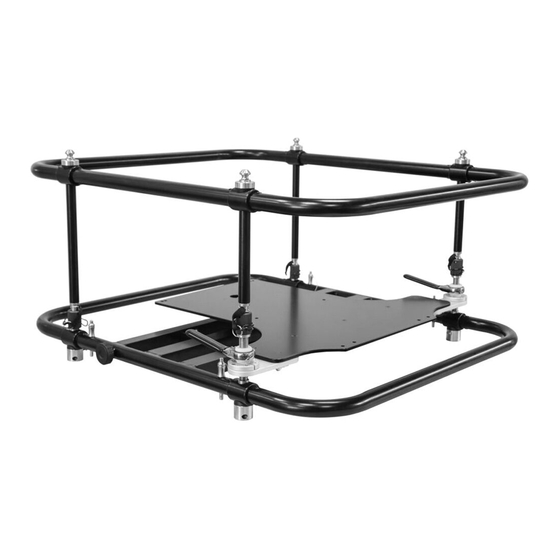
- Page 1 MODEL ET-PFD465 FRAME-EVO-P14 / P14-US Mounting frame for projectors The following projectors can be mounted in this frame: LCD Projectors PT-MZ16KL PT-MZ13KL PT-MZ10KL These installation instructions must always be provided to the customer...
- Page 2 Manual FRAME-EVO-P14 / P14-US Page 1 of 38 02.01.2020...
-
Page 3: Table Of Contents
Manual FRAME-EVO-P14 / P14-US Table of content 1. Preamble ....................... 3 1.1 FRAME-EVO-P14 / P14-US designation ..................3 1.2 Optional accessory designation ....................4 1.3 Tools required ...........................5 2. Safety instructions ..................5 3. What’s in the box? ..................11 4. Optional Accessories ................... 12 5. -
Page 4: Preamble
= model number Note: In this manual, when reference is made to the manufacturer model number it is also automatically a reference to the Panasonic EU / USA model number like described in the table above Page 3 of 38... -
Page 5: Optional Accessory Designation
= model number Note: In this manual, when reference is made to the manufacturer model number it is also automatically a reference to the Panasonic EU / USA model number like described in the table above. Page 4 of 38... -
Page 6: Tools Required
Manual FRAME-EVO-P14 / P14-US 1.3 Tools required The only tool required is a 4 mm hex key to mount the projector in the FRAME-EVO-P14 / P14-US. 4 mm hex key (Allen key) 2. Safety instructions These installation instructions must always be handed over to the installing person. Read these instructions carefully before installing the system. - Page 7 Manual FRAME-EVO-P14 / P14-US WARNINGS Installation work should only be carried out by a qualified technician. If this product is not installed correctly, serious accidents may result. Do not use the FRAME-EVO-P14 / P14-US frame outdoors. This product is made only for indoor usage. If the FRAME-EVO-P14 / P14-US frame is mounted outdoor, there are many influences like wind or rain that can have an effect on the stability of the whole system.
- Page 8 Manual FRAME-EVO-P14 / P14-US For stacking, make sure that all four locking pins pass completely through the female stacking bolt. Make sure the four male bolts enter into the correspondent female bolts and are locked. Do not install the FRAME-EVO-P14 / P14-US or the projector while people are present under the mounting zone during the installation process.
- Page 9 Manual FRAME-EVO-P14 / P14-US CAUTION Before installing the projector in the FRAME-EVO-P14 / P14-US frame, please read the projector’s user manual. When the projector has a lens attached, please remove it. The FRAME-EVO-P14 / P14-US frame with the projector inside must be installed only in an environment that is recommended by the projector manufacturer.
- Page 10 Manual FRAME-EVO-P14 / P14-US RISK SITUATIONS Risk of injury due to the possibility of falling objects during the assembly or disassembly of the FRAME-EVO-P14 / P14-US frame. Protection objective: avoid injury from falling parts. Wear appropriate safety shoes, gloves and helmet. ...
- Page 11 Manual FRAME-EVO-P14 / P14-US The fingers or the hand of the user can be caught between the outer rings and the plates or projector. Protection objective: Prevent personal injury by using safety gloves. When the adjustment of the image is made, the user must always keep his hands on the hand levers (see picture below).
-
Page 12: What's In The Box
Manual FRAME-EVO-P14 / P14-US 3. What’s in the box? FRAME-EVO-P14 / P14-US Used for projector installation Number of units: 1 Weight: 14,5 kg / 37.97 lbs 1) 7 x M6x20 ISO 7380 screws (galvanized steel 10.9) 2) 7 x Ø6 Schnorr Washer Used to secure the projector in the frame User manual and installation guide... -
Page 13: Optional Accessories
Manual FRAME-EVO-P14 / P14-US 4. Optional Accessories Please refer to “1.1 FRAME-EVO-P14 / P14-US designation” to assign the Panasonic EU and USA model numbers to the model numbers below. Please refer to chapter “10. Mounting the frame on a truss” and the following for information regarding the usability of the optional accessories. - Page 14 Manual FRAME-EVO-P14 / P14-US EVO-LINK-211 Optional accessory for truss mount installations. More information can be found in the EVO-LINK-200 series installation manual. FRAME-PF-UNI-PORAD Portrait Adapter for Projector Frames Optional accessory for portrait mode truss mount installations. Does include the EVO-LINK-200 series More information can be found in the FRAME-PF-UNI-PORAD installation manual.
- Page 15 Manual FRAME-EVO-P14 / P14-US FRAME-PF-UNI-CLP5030 Optional accessory for hanging one FRAME- EVO-P14 / P14-US or two in tandem mode on a truss. FRAME-PF-UNI-CLP5030 represents a complete set of 4 pieces. FRAME-PF-UNI-CLP30PT Optional accessory for portrait mode table installation. FRAME-PF-UNI-CLP30PT represents a complete set of 4 pieces.
-
Page 16: Fitting The Projectors In The Frame
Manual FRAME-EVO-P14 / P14-US 5. Fitting the projectors in the frame Step 1: Place the projector upside down on a suitable flat surface then remove the lens (if it is pre-installed). For easier access you may first remove the upper ring before mounting the projector. - Page 17 Manual FRAME-EVO-P14 / P14-US Torque: 4±0.5 Nm Step 3: Place the recommended number of Ø6 Schnorr Washers (2) over each corresponding hole. Secure the recommended number of M6x20 ISO 7380 screws (1) into each hole with 4 Nm torque. Ensure each screw runs through the plate and catches into the corresponding M6 hole in the projector surface.
-
Page 18: Removing The Upper Ring - Installation Version
Manual FRAME-EVO-P14 / P14-US 6. Removing the Upper Ring - Installation Version The purpose of the Installation Version is to have a quick, simple and tool free possibility to remove the Upper Ring for compact applications. Step 1: Remove the 4 x spring clips as presented in the above picture. Because the spring of the spring clip is strong, please be careful not to clamp your fingers between the spring and the attachment nut Page 17 of 38... - Page 19 Manual FRAME-EVO-P14 / P14-US Step 2: Unscrew the 4 x attachment nuts (as presented in the above picture) until they are completely loose and can be move up and down freely. Step 3: Remove the Upper Ring and you will have the Installation Version of the frame Page 18 of 38 02.01.2020...
-
Page 20: Reinstalling The Upper Ring
Manual FRAME-EVO-P14 / P14-US 7. Reinstalling the Upper Ring Step 1: Reposition the Upper Ring on the top of the Bottom Ring in such a way that the 4 x attachment nuts are lying on the corresponding position. Page 19 of 38 02.01.2020... - Page 21 Manual FRAME-EVO-P14 / P14-US Step 2: Tighten back the 4 x attachment nuts until there is no play and the attachment nuts can not be moved up or down. Step 3: In the process of attaching the Upper Ring back to the frame, as a last step, please don’t forget to reinsert the 4 x spring clips back into the attachment nut.
-
Page 22: Adjustment Options
Manual FRAME-EVO-P14 / P14-US 8. Adjustment options Roll Using the hand levers to the left and right you can adjust the position of the projector with an angle of ±2.56 degrees. You can lower or lift the front left or right corner. - Page 23 Manual FRAME-EVO-P14 / P14-US Pitch Also by using the two hand levers at the sides you can lower the projector with an angle of -3.58 degrees and lift it with an angle of +4.40 degrees. By turning the adjustment screw below the projector, you can move the back of the projector to the left with an angle of 3.73 degrees or to the...
-
Page 24: Stacking Frames
Manual FRAME-EVO-P14 / P14-US 9. Stacking frames Female bolt Male bolt Locking pin Step 1: Place the upper frame with mounted projector on top of the lower frame with mounted projector. Make sure the four male bolts enter into the correspondent female bolts. -
Page 25: Mounting The Frame On A Truss
Manual FRAME-EVO-P14 / P14-US 10. Mounting the frame on a truss To hang the frame on a truss one must use the recommended 4 x M6 or the 4 x M8 threaded holes to attach a mounting accessory like the EVO-LINK-200 series. Use only the original and recommended accessories for this procedure. - Page 26 Manual FRAME-EVO-P14 / P14-US Always secure the frame using appropriate safety steel cables. Make sure they are chosen correctly regarding strength, format and length. Please avoid high dynamic forces by ensuring that the frame will not drop more than 5 cm into the safety.
-
Page 27: Maximum Stacking Information
Manual FRAME-EVO-P14 / P14-US 11. Maximum stacking information Please refer to the tables below to confirm proper usage Do not try to setup the frame in another position as presented, because accidents can occur! With EVO-LINK-200 series Landscape Page 26 of 38 02.01.2020... - Page 28 Manual FRAME-EVO-P14 / P14-US With rigging clamps FRAME-PF-UNI-CLP5030 Distance between the rigging clamps: On X axis: 275 mm Portrait On Y axis: between 380 mm and 390 mm Distance between the rigging clamps: On X axis: 718,5 mm Landscape ...
- Page 29 Manual FRAME-EVO-P14 / P14-US With Portrait Adapter FRAME-PF-UNI-PORAD together with EVO-LINK-200 series If using FRAME-EVO-P14 / P14-US together with FRAME-PF-UNI-PORAD one of the four clamp must be removed so that only three clamps are used Portrait More information can be found in the FRAME-PF-UNI-PORAD installation manual.
- Page 30 Manual FRAME-EVO-P14 / P14-US On a table In this position one must use the FRAME-PF-UNI-CLP30PT and the frame has to be positioned with the Portrait adjustment screw on top. Landscape Not possible because of the cooling system that is located on the back side Vertical Up of the projector.
- Page 31 Manual FRAME-EVO-P14 / P14-US Installation Version – without the Upper Ring With rigging clamps FRAME-PF-UNI-CLP5030 Portrait With With rigging clamps On a table EVO-LINK-200 series FRAME-PF-UNI-CLP5030 Landscape Page 30 of 38 02.01.2020...
- Page 32 Manual FRAME-EVO-P14 / P14-US With rigging clamps FRAME-PF-UNI-CLP5030 In this case, please always be sure that the Vertical minimum distance between the back of Down the projector and the nearby surface is respected. This value can be found in the projector manual.
-
Page 33: System Maintenance And Inspection (Re-Examination)
Manual FRAME-EVO-P14 / P14-US 12. System maintenance and inspection (Re-examination) The FRAME-EVO-P14 / P14-US does not require special maintenance but a visual inspection must be done prior to every installation in which the system is involved: Before and after each installation, the M6 and M8 mounting holes must be carefully inspected, as they may get damaged during the installation of the hanging accessory. - Page 34 Manual FRAME-EVO-P14 / P14-US Bottom view: Top view: On the three screws + nuts presented on the above picture a red colour sealing wax was applied to be sure that the nuts will always be on the same position and no one will try to tighten or loosen them;...
- Page 35 Manual FRAME-EVO-P14 / P14-US Do not exchange broken or malfunctioning parts with ones that are not accredited by the manufacturer because serious injuries and property damage can occur! The inspection must be done by a qualified person! One meticulous inspection must be performed every year. For that, a qualified person needs to carefully check that none of the components are damaged or broken.
-
Page 36: Declaration Of Conformity
Manual FRAME-EVO-P14 / P14-US 13. Declaration of Conformity Page 35 of 38 02.01.2020... -
Page 37: Dimensions
Manual FRAME-EVO-P14 / P14-US 14. Dimensions 14.1 FRAME-EVO-P14 / P14-US Frame weight: 14,5 kg / 31,97 lbs; (only frame) Page 36 of 38 02.01.2020... -
Page 38: Frame-Evo-P14 / P14-Us Installation Version - Without The Upper Ring
Manual FRAME-EVO-P14 / P14-US 14.2 FRAME-EVO-P14 / P14-US Installation Version - without the Upper Ring Frame weight: 10,6 kg / 23,37 lbs; (only frame) For a possible ultra-short throw lens that will be compatible with the PT-MZ16Kl projector. Page 37 of 38 02.01.2020... -
Page 39: Imprint
Manual FRAME-EVO-P14 / P14-US Imprint EXACT solutions GmbH Lustheide 85 51427 Bergisch Gladbach GERMANY Tel.: +49 2204 9485 30 E-Mail: info@exactsolutions.de Web: www.exactsolutions.de Page 38 of 38 02.01.2020...
Need help?
Do you have a question about the ET-PFD465 and is the answer not in the manual?
Questions and answers