Advertisement
Quick Links
Advertisement

Subscribe to Our Youtube Channel
Related Manuals for Mobility Research GaitKeeper GKS20


Summary of Contents for Mobility Research GaitKeeper GKS20
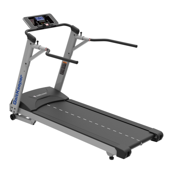
- Page 1 GaitKeeper GKS20 Treadmill ASSEMBLY MANUAL...
- Page 3 TABLE OF CONTENTS PRE ASSEMBLY GKS20 ASSEMBLY INSTRUCTIONS MAINTENANCE Thank you for purchasing our product, please save these instructions. Please do not perform or attempt any customizing, adjustments, repair or maintenance that is not described in this manual. Serial Number: Date Purchased: Location Purchased:...
-
Page 4: Tools Included
GKS20 PRE ASSEMBLY UNPACKING TOOLS INCLUDED: 1. Cut the straps, then lift the box over the unit and unpack. ‰ Allen Wrench ‰ Combination M5 Allen Wrench 2. Carefully remove all parts from the carton and inspect for any & Phillips Head Screw Driver damage or missing parts. - Page 5 CONSOLE CONSOLE SUPPORT BAR SAFETY KEY HANDLEBAR HANDLEBAR COVERS BRACKETS HANDLEBAR ADJUSTMENT POP-PIN HANDLES UPRIGHTS MOTOR COVER SIDE RAILS TRANSPORT WHEELS END CAPS BELT LEVELERS...
- Page 6 GKS20 STEP ONE 1. Take the treadmill out of the carton and place it on the a flat surface. GKS20 STEP TWO 1. Connect the Safety Switch Wire (Lower) (48) with the Safety Switch Wire (Middle) (47) which is located in the upright. 2.
- Page 7 GKS20 STEP THREE 1. Secure the Left Upright (4) and Right HARDWARE FOR STEP 3 TYPE DESCRIPTION Upright (5) on the Main Frame (1) BOLTS 3/8” X 2-1/4” using SPLIT WASHER Ø10 8 Button Head Socket Bolts (130) , FLAT WASHER Ø3/8”...
- Page 8 GKS20 STEP FOUR 1. Connect the Safety Switch Wire (Upper) (45) with the Safety Switch Wire (Middle) (47).
- Page 9 GKS20 STEP FIVE 1. Install the Console Support (6) into the Left HARDWARE FOR STEP 5 TYPE DESCRIPTION and Right Uprights (4, 5) with BOLTS 3/8” X 1-3/4” CURVED Ø10 × Ø23 × 2 Button Head Socket Bolts (133) and WASHER 1.5T 2 Curved Washers (134)
- Page 10 GKS20 STEP SIX 1. Install the Handlebar Cover (L, R)(55, HARDWARE FOR STEP 6 PART TYPE DESCRIPTION 56) on Right & Left Uprights (4, 5) and SCREWS 3.5 × 12m/m Console Support Bar (6). Then secure with 4 Sheet Metal Screws (125) by using the Combination Screw Driver (131).
- Page 11 GKS20 STEP SEVEN 1. Install Handbar Bracket (8) onto the Left HARDWARE FOR STEP 7 PART TYPE DESCRIPTION and Right Uprights (4, 5) and use Allen BOLTS 3/8”×UNC16 ×3/4” Wrench (132) to tighten FLAT WASHERS Ø3/8”×Ø19×1.5T 8 Button Head Socket Bolts (120) and 8 Flat Washer (106).
- Page 12 GKS20 STEP EIGHT 1. Insert the USB Cable in the Console (52) into the USB port on the front of the Main Frame (1).
- Page 13 GKS20 Maintenance Please tighten all screws after assembling all components.
- Page 14 GKS20 Belt Tracking 1. A 6 mm Allen wrench is provided for this adjustment. Make tracking adjustments on the left side bolt. Set belt speed at 3mph ( 5 kmph). Be aware that a small adjustment can make a dramatic difference which may not be apparent right away.
- Page 15 GKS20 Belt/Deck Lubricant 1. Every 2-3 months (or after 90 hours of use) check to see if the deck is still sufficiently lubed. A dry or sticky deck will need to be cleaned and lubed. 2. Clean between the belt and deck to remove any debris that may be trapped. Use a clean, non-fraying rag.
- Page 16 Mobility Research P.O. Box 3141 (800) 332 - 9255 Tempe, AZ 85280 GKS20 Assembly Manual © 2018 All Rights Reserved Revision: 04.19.2018 Ver. 4.0...
Need help?
Do you have a question about the GaitKeeper GKS20 and is the answer not in the manual?
Questions and answers