Table of Contents
Advertisement
Quick Links
INSTRUCTION MANUAL FOR DIAL-TYPE LEVEL INDICATORS
1. INSTRUMENT DESCRIPTION
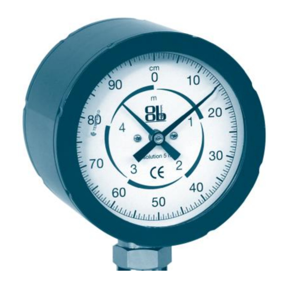
Mechanical dial-type level indicators have been designed to measure the level of fluids in small, medium and large
vessels.
The main assets are: great reliability and sturdiness, quick and easy installation and easy-readable level due to the dial
size.
The instrument does not require any power supply.
2. MODEL IDENTIFICATION
VERSION
S
up to 5 m
H
up to 20 m
MEASUR. RANGE
03
0-3 m single scale
05
0-5 m double scale
10
0-10 m double scale
20
0-20 m double scale
TLQ.
S
03
24010 Ponteranica (Bergamo) ITALY - via Serena, 10 - Phone 0039/035/4530211 - Fax 0039/035/570546 - www.officineorobiche.it-e-mail:info@officineorobiche.it
*****************************************************************************************************************************************************************
MAR.'13
OFFICINE OROBICHE S.p.A.
EXTENSION MATERIAL
brass
O
Aisi 316
J
PROCESS CONNECTION
TG
GAS thread
TN
NPT thread
FU
UNI flange
FA
ANSI flange
FD
DIN flange
CONN. MATERIAL
Carb. Steel
Aisi 316
1
3
4
5
6
O
TG
A
1
Information subject to change without notice
SERIES TLQ
A
J
FLOAT
AISI 316L Ø85x110mm
AISI 316L Ø105mm
AISI 316L Ø140mm
AISI 316L Ø300mm
Special float
TRANSMITTER
T0
No trasmitter
TS
Std. Transmitter
TE
Exia IIC T6 transmitter
TH
Hart Transmitter
TX
Hart/Exia Transmitter
C0
No alarms
CS1-4
1-4 Standard alarms
CE1-2
1-2 Exd IIC T6 alarms
CP1-4
1-4 PNP proximity alarms
CN1-4
1-4 NPN proximity alarms
CR1-4
1-4 NAMUR proximity alarms
T0
C0
XX
ALARMS
N0N-STANDARD VERSION
1/9
IST/164-I
Advertisement
Table of Contents

Related Manuals for OFFICINE OROBICHE TLQ Series


Summary of Contents for OFFICINE OROBICHE TLQ Series
- Page 1 OFFICINE OROBICHE S.p.A. INSTRUCTION MANUAL FOR DIAL-TYPE LEVEL INDICATORS SERIES TLQ 1. INSTRUMENT DESCRIPTION Mechanical dial-type level indicators have been designed to measure the level of fluids in small, medium and large vessels. The main assets are: great reliability and sturdiness, quick and easy installation and easy-readable level due to the dial size.
-
Page 2: Operating Principle
OFFICINE OROBICHE S.p.A. 3. OPERATING PRINCIPLE Operation is based on the buoyancy principle. The float is combined with a very high-precision clockworks gear-operated system, which assure an accurate and repeatable level measurement in the vessel. The float (1), which contains a permanent magnet (2), slides along a rod (3) that holds inside a further magnet (4) connected to a rod (5). - Page 3 OFFICINE OROBICHE S.p.A. Assembling sequence: 1. Insert the float into the rod with the reference text (“TOP”) upwards, then place the retainer in the dedicated seat located at the lower end of the rod. 2. Insert the rod with the float into the vessel and secure the whole set. In cases when the float is larger than the diameter of the inlet nozzle, insert it through the manhole on a vessel's side.
- Page 4 OFFICINE OROBICHE S.p.A. 4.2 WIRING The wiring shall be performed in accordance with the diagrams provided, and the cables shall suit the intended use of the instrument (as regards temperature, environment and the like). The electrical wiring shall be carried out in accordance with the regulations in force in the country of installation.
-
Page 5: Setting At Work
OFFICINE OROBICHE S.p.A. -TRANSMITTER 4/20mA series TS-TE-T4-TX x TS-T4 x TE-TX wiring 5 SETTING AT WORK Make sure that the use of the instrument does not exceed the intended use (i.e. pressure and temperature values and the like) and ensure the measurement made is correct by changing a few times the level of the fluid in the vessel. -
Page 6: Maintenance
OFFICINE OROBICHE S.p.A. Calibrating alarm contacts Alarm contacts are generally factory pre-set. In case of unexpected calibration to be performed at the building stage, take the following actions: -remove the rear cover and loosen the cam block screws; -place the float at the desired heights and turn the cams until the contact operates the switching;... -
Page 7: Dimensional Drawing
OFFICINE OROBICHE S.p.A. 8 DIMENSIONAL DRAWING Dimensioning values required C=Connections L=Range E=Extension F=Float D=Extension connection TLQ-S TLQ-H Ø160 Ø220 THREADED 3/4 GAS-M THREADED 1.1/4" GAS-F UNI DN 20-150 PN10-16 UNI DN 32-150 PN10-16 FLANGED FLANGED ANSI 3/4" - 6" ANSI 150 ANSI 1"1/4 - 6"... -
Page 8: 10. Troubleshooting
(shipment fees not included) all damaged parts free, provided that the failure does not ensue from incorrect use. OFFICINE OROBICHE shall never be held responsible for any incorrect use of their products when these are used for purposes other than those mentioned in the specifications approved at the order stage. -
Page 9: Final Remarks
5) Specification of the fluids that have been used with the instrument. The instrument shall be returned perfectly clean and free from dust or deposits. Otherwise, OFFICINE OROBICHE reserves the right not to carry out the servicing and return the instrument to the sender.
Need help?
Do you have a question about the TLQ Series and is the answer not in the manual?
Questions and answers