
Related Manuals for Ritron DTXM-NXDN Series


Summary of Contents for Ritron DTXM-NXDN Series
- Page 1 RITRON, INC. 12-2020 RITRON MODELS DTXM-NXDN SERIES PROGRAMMABLE FM TRANSCEIVER MODULES MAINTENANCE & OPERATING MANUAL FOR USE ONLY BY AUTHORIZED SERVICE/MAINTENANCE PERSONNEL...
-
Page 2: Table Of Contents
TABLE OF CONTENTS DTXM MODULES INTRODUCTION GENERAL MODEL IDENTIFICATION FCC/IC REGULATIONS SPECIFICATIONS GENERAL TRANSMITTER RECEIVER DTXM INPUT/OUTPUT CONNECTOR ACCESSORIES OPERATION CHANNEL SELECTION POWER SUPPLY VOLTAGE CURRENT DRAIN vs SUPPLY VOLTAGE DUTY CYCLE/KEY-DOWN LIMITATIONS OPERATING MODES PROGRAMMING PC PROGRAMMING KIT LOADING THE PROGRAMMING SOFTWARE COMPUTER SOFTWARE COPYRIGHTS USING THE PROGRAMMING SOFTWARE PROGRAMMER MENUS... -
Page 4: Introduction
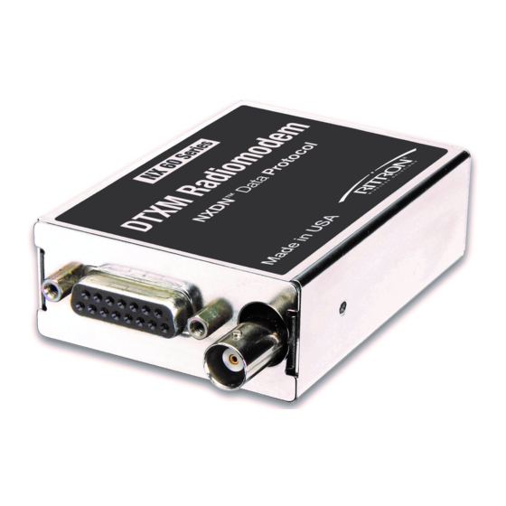
INTRODUCTION GENERAL The RITRON DTXM Plus modules are programmable 2-way radios, which operate either in the VHF or UHF professional FM communications bands as well as a number of other bands in the 220 MHz and 350 MHz region. Each of four channels can be programmed to contain a unique set of operating frequencies. -
Page 5: Fcc/Ic Regulations
F designates the regulator option I=Internal regulator (10-16 VDC operation with regulated RF power amplifier) D=No regulator (7.5 VDC operation) L=RF PA is unregulated, but the remainder of the modem is regulated (10-watt versions) Example: A DTXM-160-OBN6I would be a VHF module for operation between 136 and 174 MHz with a BNC RF connector, narrow (12.5 kHz channel spacing) IF bandwidth, 6 watts maximum output power, and an internal regulator to allow operation from 10 to 15 volts. - Page 6 This 2-way radio uses electromagnetic energy in the radio frequency (RF) spectrum to provide communications between two or more users over a distance. It uses radio frequency (RF) energy or radio waves to send and receive calls. RF energy is one form of electromagnetic energy. Other forms include, but are not limited to, electric power, sunlight and x-rays.
- Page 7 Ritron accessories supplied or designated for this product. Use of other accessories may not ensure compliance with the FCC’s RF exposure guidelines, and may violate FCC regulations. • For a list of Ritron approved accessories see this user manual, or visit the following website which lists approved accessories: www.ritron,com...
- Page 8 INFORMATIONS DE SENSIBILISATION ET DE CONTRÔLE À L'EXPOSITION AUX ÉNERGIES RF, ET INSTRUCTIONS OPÉRATIONNELLES POUR LES EXIGENCES D'UTILISATION PROFESSIONNELLE DE LA FCC: AVANT D'UTILISER CETTE RADIO À 2 VOIES, LISEZ CES INFORMATIONS IMPORTANTES SUR LA SENSIBILISATION ET LE CONTRÔLE À L'ÉNERGIE RF ET LES INSTRUCTIONS OPÉRATIONNELLES POUR VOUS ASSURER LA CONFORMITÉ...
- Page 9 allant jusqu'à 50% de conversation et 50% d'écoute et est autorisée par la FCC pour une utilisation professionnelle. En termes de mesure de l'énergie RF pour se conformer aux directives d'exposition de la FCC, votre antenne radio émet de l'énergie RF mesurable uniquement lorsqu'elle émet (pendant la conversation), pas lorsqu'elle reçoit (écoute) ou en mode veille.
- Page 10 RF de la FCC et peut enfreindre les réglementations FCC. • Pour une liste des accessoires approuvés par Ritron, consultez ce manuel de l'utilisateur ou visitez le site Web suivant qui répertorie les accessoires approuvés: www.ritron, com...
-
Page 11: Specifications
SPECIFICATIONS GENERAL DTXM-160-0 FCC ID: AIERIT51-16006 (Pending) IC ID: 1084A-RIT5116006 (Pending) FCC Rule Parts Industry Canada Rule Parts RSS-119 Frequency Range DTXM-160-0 136-174 MHz Number of Channels Transmit/Receive Spacing Up to the span of the sub-band Mode of Operation Simplex or Half Duplex Frequency Control PLL Synthesizer Channel Increment (Synthesizer step size) -
Page 12: Transmitter
TRANSMITTER Operating Bandwidth Up to the span of the sub-band RF Output Power(internally adjustable) 6 watt version 1 to 6 watts (2.5 watts min. recommended) Duty Cycle 5 to 100 % depending upon voltage and power level (see chart elsewhere in manual) RF Load Impedance 50 ohms... -
Page 13: Receiver
RECEIVER Operating Bandwidth Up to span of the sub-band Sensitivity (12 dB SINAD @ 1 kHz w de-emphasis) 0.25 uV (-119.0 dBm) RF Input Impedance 50 ohms nominal Adjacent Channel Selectivity +/-6.25 kHz w very narrow IF 45 dB min. +/- 12.5 kHz w narrow IF 60 dB min. -
Page 14: Dtxm Input/Output Connector
DTXM INPUT/OUTPUT CONNECTORS DB-15 Connector Pinout Pin Number Name Description Comments Audio/Mic In External Audio Input Wideband input for data. Audio Out Auxiliary Output Wideband output for data. Speaker Audio PA Output Output of audio PA. Channel Select low bit RSSI Receive Signal Strength Analog Receive Signal Strength... - Page 15 -130 dBm signal to about 4 VDC for signals at or above -60 dBm. RAW SUPPLY- Supply voltage input. +10VDC to +16VDC. DISC OUT- RD- Connect via RITRON DTXP-PCPK PC Programming Kit to computer for programming the unit. TD-Connect via RITRON DTXP-PCPK PC Programming Kit to computer for programming the unit.
-
Page 16: Accessories
ACCESSORIES Note: Programming kits are for use by authorized service/maintenance personnel only. The Programming Kit for DTXM Plus radios (via compatible computer) is model DTXM-NXDN- PCPK-1. It includes: 1) Programming Software, DTXM-NXDN-PCPS-1. 2) DB-9 to DB-15 connector cable with power cable. 3) 9-Pin to USB Adapter, 2147C002. -
Page 17: Operation
1 = Logic high Note: Due to the internal pull-up resistors, the unit defaults to channel 8 if the channel pins are left open (unconnected). Channel 4 would be the nominal channel when the Ritron programmer is connected. A change in the channel selection in receive will cause the receiver to operate on the new channel. -
Page 18: Duty Cycle/Key-Down Limitations
Also, a fan option is available from Ritron which can significantly increase the duty cycle, up to 100% at room temperature in some cases. Contact Ritron for additional information on these options and special instructions on attaching heat sinks without compromising the mechanical integrity of the RF PA module. -
Page 19: Operating Modes
AC coupled, but can be modified for DC coupling. This requires replacing a coupling capacitor with a zero-ohm resistor. Contact Ritron for details on this modification. The AUDIO OUT is always de-emphasized, but its gain can be programmed. This output can drive 8- ohm speaker-type loads. -
Page 20: Programming
The end user/system integrator would then bear the responsibility of obtaining certification or operating in a frequency band where certification is not required. Contact RITRON for details. Note: Most modems will connect directly to the DTX without requiring any special modifications or programming. -
Page 21: Computer Software Copyrights
RITRON, Inc. except for the non-exclusive, royalty fee license to use that arises in the sale of a product, or as addressed in a written agreement between RITRON, Inc. and the purchaser of RITRON, Inc. products. - Page 22 4. Update Radio-This button is used to update the radio with all of the changes that have been made via the programmer. Although the radio accepts changes as they are made via the programmer, the changes are volatile i.e. they are lost when the radio is powered off. Clicking on this button makes the changes non-volatile so that they are saved and stored permanently unless changed via the programmer.
- Page 23 RX Discriminator Coupling- Selects whether the coupling from the discriminator output on the RF board is AC or DC coupled to the control/loader board. Since the audio outputs of the control/loader board are AC coupled, this function is normally set for AC as well. Setting this function to DC will extend the low frequency receiver response somewhat, but makes the audio output subject to clipping due to DC offsets on the discriminator output.
- Page 24 SUMMARY 6.5.4 The summary page summarizes the information shown on the other three pages and, in addition, includes the model and serial number of the unit. RESTORE EEPROM 6.5.5 This selection is used to load a previously saved radio configuration file to the radio connected to the programmer.
-
Page 25: Maintenance
The parts within the shield are low failure items; repair or replacement should not be required unless the RF board is mishandled. If failure of a part within the shield is deemed to have occurred, the RF board should be returned to RITRON for service or replacement. -
Page 26: Hardware Options
The AUX OUT output is normally AC coupled through C399. If DC coupling is desired, an 0805 size SMD zero ohm jumper resistor (RITRON P/N 47100000) must be soldered in the location of MR384. (In lieu of a zero ohm jumper, a small piece of wire may be carefully soldered between the pads.) The AUX OUT DC level then becomes nominally 1.67 volts.
Need help?
Do you have a question about the DTXM-NXDN Series and is the answer not in the manual?
Questions and answers