NimbeLink Skywire NLSWDK User Manual
Hide thumbs
Also See for Skywire NLSWDK:
- User manual (26 pages) ,
- Windows networking manual (10 pages) ,
- Manual (7 pages)
Advertisement
Quick Links
Advertisement

Related Manuals for NimbeLink Skywire NLSWDK


Summary of Contents for NimbeLink Skywire NLSWDK
- Page 1 PN 30005 rev 10 NimbeLink Corp All Rights Reserved 1 ...
- Page 2 1. Introduction 1.1 Orderable Part Numbers 1.2 Product Overview 1.3 Block Diagram 2. Connect to Kit using a PC 2.1 Unpack Kit Contents 2.2 Skywire ™ Placement 2.3 Attach Antenna to Baseboard 2.4 Ensure header J6 is shorted with 2 pin Jumper 2.5 Plug in 12V Power Supply to connector J15 2.6 Plug USB cable into connector J14 and PC 2.7 Press and hold button S1 to power on the modem 2.8 Open Tera Term or similar terminal emulator 2.9 Test Serial Communication 2.10 Test Signal Strength 2.11 Activate Modem (onetime step) 2.12 SIM Card Detection (GSM Only) 2.13 Send Modem Activation String (1xRTT and EVDO only) 2.14 Setup PDP Context (GSM and LTE Only) 2.15 Test Network Communication 3. Common Next Steps PN 30005 rev 10 NimbeLink Corp All Rights Reserved 2 ...
-
Page 3: Orderable Part Numbers
necessary signals for easy connection to any device. The modem supports I/O levels from 1.655.5V, simplifying connection to other systems. PN 30005 rev 10 NimbeLink Corp All Rights Reserved 3 ... -
Page 4: Block Diagram
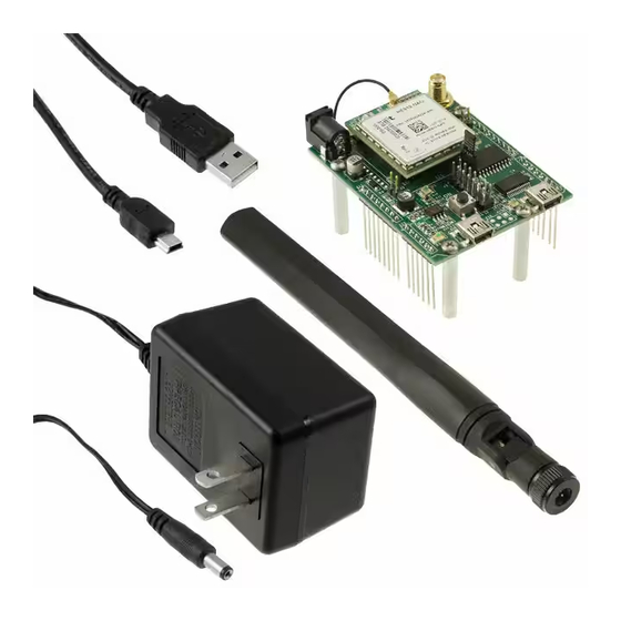
1.3 Block Diagram *X2 and X3 U.FL connectors not present on all modems. PN 30005 rev 10 NimbeLink Corp All Rights Reserved 4 ... - Page 5 (connector J5) is used for Telit firmware updates to the modem and is not used in this section. 2.1 Unpack Kit Contents Note: The Skywire™ Development Kit also comes with SIM cards (not pictured) PN 30005 rev 10 NimbeLink Corp All Rights Reserved 5 ...
-
Page 6: Skywire™ Placement
by one row. Check pin alignment BEFORE applying power to prevent modem damage. PN 30005 rev 10 NimbeLink Corp All Rights Reserved 6 ... - Page 7 2.3 Attach Antenna to Baseboard Antenna screws onto SMA connector with a clockwise rotation 2.4 Ensure header J6 is shorted with 2 pin Jumper This enables USB to UART communication between the PC and the modem. PN 30005 rev 10 NimbeLink Corp All Rights Reserved 7 ...
- Page 8 2.5 Plug in 12V Power Supply to connector J15 2.6 Plug USB cable into connector J14 and PC PN 30005 rev 10 NimbeLink Corp All Rights Reserved 8 ...
- Page 9 > 15 seconds 1 second < t NLSWLTETEUG < 2 seconds No activity w h t > 30 seconds 1 second < t NLSWLTEGELS3 < 2 seconds Solid on w h *Note: Depending on your modem and depending on the setup, the modem may be available for use before t w PN 30005 rev 10 NimbeLink Corp All Rights Reserved 9 ...
- Page 10 After pressing the Enter key, the terminal program will respond with: OK PN 30005 rev 10 NimbeLink Corp All Rights Reserved 10 ...
- Page 11 Values of y y Bit Error Rate (in percent) 0 Less than 0.2% 1 0.2% to 0.4% 2 0.4% to 0.8% 3 0.8% to 1.6% 4 1.6% to 3.2% 5 3.2% to 6.4% 6 6.4% to 12.8% 7 More than 12.8% 99 Not known or not detectable PN 30005 rev 10 NimbeLink Corp All Rights Reserved 11 ...
- Page 12 A NimbeLink staff member will contact you to activate the modems. To activate the NEO SIM for GSM modems, please follow the directions printed ...
- Page 13 minutes . The terminal should respond with: OK #OTASP: 0 #OTASP: 1 #OTASP: 2 NO CARRIER For all other responses, review network status responses online. 2.14 Setup PDP Context (GSM and LTE Only) Applies to: NLSWGPRS NLSWHSPAP NLSWHSPAPE NLSWHSPAPG NLSWLTETSVG NLSWLTETNAG NLSWLTETEUG PN 30005 rev 10 NimbeLink Corp All Rights Reserved 13 ...
- Page 14 and Message Service Centers”, located at the following URL: http://nimbelink.com/wpcontent/uploads/2014/10/Skywire_Defining_PDP_Contxts_MsgServ_Ctrs.pdf To verify that the APN was set correctly, in the terminal program type the command: AT+CGDCONT? followed by the Enter key, and the terminal should respond with: +CGDCONT: 1,”IP”,” A PN ” as well as the other PDP context information on the device. To enable this setting, in the terminal ...
- Page 15 key, and the terminal should respond with: OK To get the specific APN setting that you need, please contact Verizon or contact NimbeLink. To verify that the APN was set correctly, type the command: AT+CGDCONT? followed by the Enter key, and the terminal should respond with: +CGDCONT: 3, “IP”, “vzwinternet” as well as the other PDP context information on the device. To enable this setting, in the terminal program type the command: AT#SGACT=3,1 followed by the enter key, and the terminal should respond with: #SGACT: www.xxx.yyy.zzz where w ww.xxx.yyy.zzz is the Skywire™ modem’s IP address. If the A T#SGACT command does not work, the terminal will respond with #ERROR and further setup may be necessary. Check the signal strength with A T+CSQ t o verify the Skywire™...
- Page 16 is getting an acceptable signal. Otherwise, consult the Nimbelink AT Command Manual for ...
- Page 17 Arduino. Please consult these application notes on the Skywire™ Development Kit page ( h ttp://nimbelink.com/skywiredevelopmentkit/ ) for specific examples of each type of operation. PN 30005 rev 10 NimbeLink Corp All Rights Reserved 17 ...
Need help?
Do you have a question about the Skywire NLSWDK and is the answer not in the manual?
Questions and answers