Table of Contents
Advertisement
Quick Links
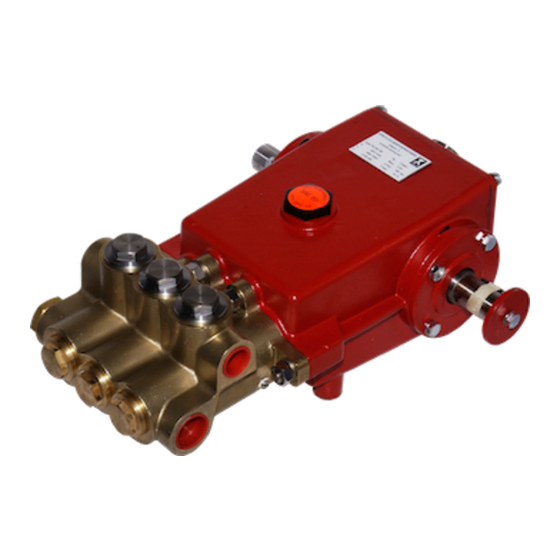
Montageanleitung Baureihe P41
Ventil- und Dichtmanschetten
Removal/Assembly - P41 Valve and Seal
Ventildemontage Druckseite
Stopfen herausdrehen. (Bild 1)
Federspannschale mit
(Bild 2)
Ventilfeder mit Spitzzange herausnehmen. (Bild 3)
Ventilplatte herausnehmen. (Bild 4)
Abzieher (Fa. Hoffmann 882600 Gr.3) in den Ventilsitz
stecken, durch drehen aufspreizen. (Bild 5)
Ventilsitz mit dem Abzieher herausnehmen. (Bild 6)
O-Ring am Ventilsitz entfernen (Bild 7)
Spitzzange herausnehmen.
Bild 2
Bild 4
Bild 6
Dismantling Valves on the Discharge Side
Screw out the plugs (photo 1).
Bild 1
Remove the spring tension cap with a taper-nose pliers
(photo 2).
Take out valve spring with a taper-nose pliers (photo 3).
Remove the valve plate (photo 4).
Put the extractor tool (Messrs Hoffmann 882600 size 3)
on to the valve seat and turn to lock (photo 5).
Pull out the valve seat (photo 6).
Take the O-ring off the valve seat (photo 7).
Bild 3
Bild 5
Bild 7
D1773 0306S
Advertisement
Table of Contents

Related Manuals for Speck P41


Summary of Contents for Speck P41
- Page 1 Montageanleitung Baureihe P41 Ventil- und Dichtmanschetten Removal/Assembly - P41 Valve and Seal Ventildemontage Druckseite Dismantling Valves on the Discharge Side Stopfen herausdrehen. (Bild 1) Screw out the plugs (photo 1). Bild 1 Federspannschale mit Spitzzange herausnehmen. Remove the spring tension cap with a taper-nose pliers (Bild 2) (photo 2).
- Page 2 Ventilmontage Druckseite Valve Assembly on the Discharge Side O-Ring in Ventilsitz einlegen. (Bild 8) Place the O-ring in the groove of the valve seat (photo 8) Ventilplatte mit Kugelfläche nach unten einlegen. (Bild 9) Insert the valve plate flat side up (photo 9). Ventilfeder einlegen, Feder muss senkrecht auf dem Put the valve spring on the valve plate making sure the Ventilteller stehen.
- Page 3 Ventil- und Dichtmanschettendemontage Saugseite Valve and Seal Sleeve Disassembly on Suction Side Stopfen herausdrehen (Bild 16) Screw out plugs (photo 16). Saugventilaufnahme mit einer Spitzzange herausneh- Remove the suction valve retainer with a taper-nose pli- men (Bild 17). ers (photo 17). Bild 16 Bild 17 Zerlegen der Saugventilaufnahme:...
- Page 4 Dichtmanschettendemontage: Disassembling the Seal Sleeves Druckfeder herausnehmen (Bild 24). Take out the pressure spring (photo 24). Dachmanschetten, Stützring und Druckring mit weichem Tap out the V-sleeves, support ring and pressure ring Stab (Kunststoff) d=31 herausklopfen (Bild25). with a Ø31 plastic rod (photo 25). Ausgedrückte Dachmanschetten mit Stütz- und Druck- Disassembled V-sleeves with support and pressure ring ring (Bild26).
- Page 5 Saugventilaufnahme Montage: Assembling the Suction Valve Retainer O-Ring an der Saugventilaufnahme montieren. (Bild 33) Put the O-ring on the suction valve retainer (photo 33). O-Ring an dem Ventilsitz montieren. (Bild 34) Put the O-ring on the valve seat (photo 34). Bild 33 Bild 34 Druckfeder einlegen, Feder muss senkrecht stehen.
- Page 6 Leckagerückführdichtung Demontage: Disassembling Drip-Return Seals Sicherungsring entfernen (Bild 41) Remove the safety ring (photo 41). Druckring entfernen (Bild 42) Remove the pressure ring (photo 42). Dichtung entfernen (Bild 43) Remove the seal (photo 43). Bild 41 Bild 42 Bild 43 Stützring entfernen (Bild 44) Remove the support ring (photo 44).
- Page 7 Montageanleitung Fixing and Removing the Ventilgehäuse Valve Casing Ventilgehäuse Demontage Taking off the valve casing Kühlung entfernen (Bild1) Remove coolant tubes (photo 1). Ventilgehäuse Verschraubung lösen. (Bild 2) Screw off the valve casing fixing screws (photo 2). Bild 1 Bild 2 Ventilgehäuse mit Kunststoffhammer vorsichtig, gerade Using a plastic hammer, knock off the valve casing nach vorne vom Antrieb wegklopfen.
- Page 8 Ventilgehäuse Montage Mounting the Valve Casing Zwei Plunger auf gleiche Höhe stellen, Ventilgehäuse Position two plungers at the same height. Mount the gerade aufsetzen. (Bild 6) valve casing straight on (photo 6). Auf den richtigen Sitz der Zentrierhülsen achten. (Bild 7) Make sure the fixing screws are correctly aligned (photo 7).
Need help?
Do you have a question about the P41 and is the answer not in the manual?
Questions and answers