
Subscribe to Our Youtube Channel
Related Manuals for Delta OHM HD402 Series


Summary of Contents for Delta OHM HD402 Series
- Page 1 English Operating manual Pressure ON/OFF relay switches HD402TR…L series Companies / Brands of GHM www.deltaohm.com Keep for future reference.
-
Page 2: Table Of Contents
TABLE OF CONTENTS INTRODUCTION ....................3 TECHNICAL CHARACTERISTICS ................4 INSTALLATION ..................... 6 ..................7 LECTRICAL CONNECTIONS ....................7 ONFIGURATION ALARM OPERATING MODES ................11 INSTRUMENT STORAGE ..................13 ... -
Page 3: Introduction
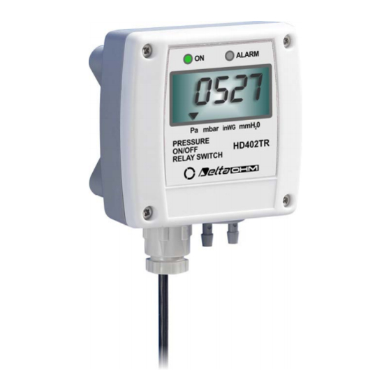
1 INTRODUCTION The series of pressure ON/OFF relay switches HD402TR...L is suitable for controlling the relative pressure with respect to atmosphere or differential pressure in the range from ±250 Pa to ±200 kPa. If the set threshold value is exceeded, the relay switch output is activated, the front alarm LED lights up and an audible alarm sounds. -
Page 4: Technical Characteristics
2 TECHNICAL CHARACTERISTICS Sensor Piezoresistive, High stability Measuring range From ±250 Pa to ±200 kPa both relative and differential Refer to table 1 Resolution Refer to table 2 Accuracy @ 25 °C ± 1.5% f.s. nominal for HD402TR1L ± 0.75% f.s. nominal for HD402TR2L ±... - Page 5 TAB. 2: resolution Model mbar inchH mmHg HD402TR1L 0.001 0.01 0.001 HD402TR2L 0.01 0.01 HD402TR3L 0.01 0.01 0.001 HD402TR4L 0.01 HD402TR5L 0.01 IMENSIONS NTERNAL VIEW Power LED Alarm LED Buttons for configuration and manual zeroing Dip switches Terminal header Serial port Pressure inputs HD402TR V1.0...
-
Page 6: Installation
3 INSTALLATION The sensor and the electronics are housed in a rugged plastic case with IP 65 protec- tion degree. By opening the lid, 3 mm diameter holes are available so to allow secur- ing the base of the instrument directly to a panel or to the wall. The instrument can be mounted in any position, but typically it is secured on a vertical wall with the pressure inputs facing down. -
Page 7: Electrical Connections
3.1 E LECTRICAL CONNECTIONS At power on, the alarm LED blinks quickly while the instrument information is displayed. 3.2 C ONFIGURATION The instrument can be configured by using the dip switches (for the unit of measurent) and the buttons (for alarm settings) on the circuit board or via the COM AUX serial port. The choice of the configuration mode is done with the dip switch 1: •... - Page 8 • Connect the COM AUX serial port of the instrument to the RS232 port (via the RS27 cable) or USB (via the cable CP27) of the PC. If you use the CP27 cable, in- stall the USB drivers on your PC. •...
- Page 9 Command Description ART1 Reads the threshold 1 value AWT2snnnn Sets the threshold 2 value to snnnn (“s” is the sign of the value) Default: pressure value corresponding to 70% of the full scale ART2 Reads the threshold 2 value AWHnnnn Sets the hysteresis value to nnnn Default: pressure value corresponding to 10% of the full scale Reads the hysteresis value...
- Page 10 • Alarm operating mode (EDGE): o Above threshold (RISE): alarm is on if measurement is greater than threshold 1 o Below threshold (FALL): alarm is on if measurement is less than threshold 1 o Outside thresholds (OUTS): alarm is on if measurement is less than threshold 1 or greater than threshold 2 •...
-
Page 11: Alarm Operating Modes
4 ALARM OPERATING MODES Above threshold (RISE): the alarm is turned on if the measurement is greater than threshold 1 for more than T1 seconds. The alarm is turned off when the measurement becomes less then threshold 1 minus the hysteresis for more than T2 seconds. The up arrow on the left of the display is shown when this mode is selected. - Page 12 When the measurement is in alarm, the red LED lights up, the buzzer is on (if enabled) and the relay is switched (depending on the chosen relay operating mode). While in alarm, the buzzer can be stopped (only for the current event) by short press- ing the button B1.
-
Page 13: Instrument Storage
INSTRUMENT STORAGE Instrument storage conditions: • Temperature: -20...+70 °C. • Humidity: less than 90 %RH no condensation. • In storage, avoid places where: • humidity is high; • the instrument is exposed to direct sun radiation; • the instrument is exposed to a high temperature source; •... -
Page 14: Ordering Codes
Connection cable with built-in USB/RS232 converter. USB connector on the PC side and 3-pole connector on the instrument side. DELTA OHM metrology laboratories LAT N° 124 are ISO/IEC 17025 accredited by AC- CREDIA for Temperature, Humidity, Pressure, Photometry / Radiometry, Acoustics and Air Velocity. - Page 16 All DELTA OHM instruments are subject to accurate testing, and are guaranteed for 24 months from the date of purchase. DELTA OHM will repair or replace free of charge the parts that, within the warranty period, shall be deemed non efficient according to its own judgement. Complete replacement is excluded and no damage claims are accepted.
- Page 17 GHM GROUP – Delta OHM | Delta Ohm S.r.l. a socio unico Via Marconi 5 | 35030 Caselle di Selvazzano | Padova | ITALY Phone +39 049 8977150 | Fax +39 049 635596 www.deltaohm.com | info@deltaohm.com The quality level of our instruments is the result of the constant development of the product. This may produce some differences between the information written in this manual and the instrument you have purchased.
- Page 18 GHM GROUP – Delta OHM | Delta Ohm S.r.l. a socio unico Via Marconi 5 | 35030 Caselle di Selvazzano | Padova | ITALY Phone +39 049 8977150 | Fax +39 049 635596 www.deltaohm.com | info@deltaohm.com V1.0 05/06/2019...
Need help?
Do you have a question about the HD402 Series and is the answer not in the manual?
Questions and answers