
Related Manuals for EcoloxTech E-1200

Summary of Contents for EcoloxTech E-1200
- Page 1 E-1200 System prebuilt with pH Control Installation & Operation Manual EcoloxTech Tel. +1 954-900-6070 service.ecoloxtech.com...
-
Page 2: Table Of Contents
Table of Contents System parts System parts description Backflow preventer Water filter Dosing unit Holding tank Pressure reduction valve Flow control valve Level / pump control Installation System process Process steps Water connection System Power connection Level sensor / pump Brine (NaCl) E1200 brine hose connection. -
Page 3: System Parts
System parts Picture 1 Shows system components, arrows shows flow direction Backboard with pH control and system bracket (backboard not shown on picture) Back flow preventer Water filter Dosing units Holding tank with float valve Pressure reducer Flow control E-240 or 1200 unit Control box Pump/level Level sensor HOCl storage tank (option, not on picture) -
Page 4: Backflow Preventer
System parts description Backflow preventer The backflow preventer (a) is installed to protect the water system from being contaminated in the case of a backflow. The backflow preventer uses an atmospheric vent for any abnormal situation. This vent is therefore to be kept unobstructed. Keep in mind that water might come out of this vent. -
Page 5: Holding Tank
Flow control valve The flow control valve (f) can adjust the flow though the system. The flow can be adjusted to anything within the system flow range. For the E-1200 that is 4 to 24 liter/minute. E-240 is 1 to 5 liter/min. -
Page 6: Installation
Installation The system is intended to be installed vertically on a wall. The system is intended to be installed vertically on a wall and will not work correctly if laying down. Installation hardware is not included with the system, and customer will have to supply their own. Picture 10 Installation overview with part numbering. -
Page 7: Water Connection
Filter and additional hose is included in the system. Additional information on the specific system can be found in the unit’s manual. E1200 unit: https://www.ecoloxtech.com/pdf/e1200soperationmanual.pdf E240 unit: http://ecoloxtech.com/pdf/e240soperationmanual.pdf Power connection Depending on what options have been chosen, the power is connected differently. The pH control part of the setup does not use electrical power for its operation. -
Page 8: Brine (Nacl)
Brine (NaCl) The brine connection depends on the system being used. The E240 unit has an internal brine tank, so no further action is needed. The E1200 unit uses an external brine tank (NaCl). Included in the system is a 1/8” hose and filter (see picture 11 & 12). Use filter and hose to connect external brine tank to the E1200 system. -
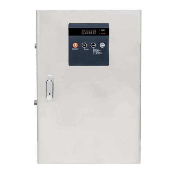
Page 9: Level / Pump Control
Level / Pump control The control box (12) is installed if the optional level sensor was added. The programmable LED display will show the tank level as a percentage of the sensor scale. The LED display is used to control the unit start/stop. The will also stop the distribution pump from running dry when tank level is too low or signal is outside normal range. -
Page 10: System Start-Up
System start-up Make sure all topics in the installation part of this manual is resolved before starting the start-up phase. Depending on our specific setup, you might have additional parts to consider. Step by step Make sure all relevant parts for your system is installed and ready, as described in the installation section. Make sure system (9) is not turned on at this time. -
Page 11: Calibrating The Level Sensor
Turn the system on. If you have the control box turn that on as well If you have the control box and level sensor, then jump to the “calibrating the level sensor” before continuing. Run the complete system and test the pH of the final product. The pH does most likely need some minor adjustment here to get the desired pH level. -
Page 12: Spare Parts List
(SKU: P-4516) (SKU: T-4552) 3/4” MPT x Socket PVC Male Adapter 3/4” FPT PVC Gate Valve E-1200 (SKU: E-1200) Sch 40 (SKU: P-4512) (SKU: P-4377) 3/4” PVC Sch 40 Pipe 3/4” Insert x 3/4” MPT Adapter Elbow 1/4” OD Silicone Tubing...
Need help?
Do you have a question about the E-1200 and is the answer not in the manual?
Questions and answers