
Related Manuals for Technoton DUT-E AF

Summary of Contents for Technoton DUT-E AF
- Page 1 FUEL LEVEL SENSORS DUT-E А5 DUT-E CAN DUT-E АF DUT-E А10 (model code 116) DUT-E 232 DUT-E F DUT-E 485 DUT-E I SK DUT-E service adapter OPERATION MANUAL (includes Service DUT-E software manuals) Version 8.1...
-
Page 2: Table Of Contents
1.3 Design and operation principle ................15 1.4 Technical specifications ..................17 1.4.1 Main specifications ..................17 1.4.2 Specifications of DUT-E AF output signal ............18 1.4.3 Specifications of DUT-E A5/A10/F/I output signal ..........19 1.4.4 Specifications of DUT-E 232/485 output signal ..........20 1.4.5 Specifications of DUT-E CAN output signal ............ - Page 3 5.5 Additional accessories ..................92 6 Diagnostics and troubleshooting ................. 93 6.1 DUT-E with analog output ..................93 6.2 DUT-E with frequency output ................94 6.3 DUT-E with digital output ..................95 DUT-E fuel level sensors. Operation manual. Version 8.1 © Technoton, 2020...
- Page 4 Annex E DUT-E profile printed copy ................113 Annex F DUT-E log file example ..................114 Annex G Electromagnetic compatibility specifications of DUT-E ......... 115 Annex H Videography ....................116 DUT-E fuel level sensors. Operation manual. Version 8.1 © Technoton, 2020...
-
Page 5: Revision History
- sensors electromagnetic compatibility; - taking into account the dead zone while creating the tank calibration table; - additional sensors accessories. 3) The structure of the document external links is introduced. DUT-E fuel level sensors. Operation manual. Version 8.1 © Technoton, 2020... -
Page 6: Structure Of External Links
Structure of external links DUT-E/DUT-E 2Bio/DUT-E GSM. Installation manual Document Center CAN j1939/S6 Telematics interface. Operation manual Part S6 Data Base S6 Website JV Technoton Website Page DUT-E Page DFM Page CANUp Technoton Engineering Website Part Technical support Part Software/Firmware YouTube Technoton ORF 4 Website DUT-E fuel level sensors. -
Page 7: Terms And Definitions
(e.g. – Onboard power supply limit/Minimum). ORF 4 — is the by JV Technoton developed for receiving and processing Onboard reports via Internet, displaying Operational Data overlapped on area maps, information storage in database and Analytical reports generation upon user’s request. - Page 8 (FM) unit-embedded component of hardware and software combination, executing a group of special functions. Uses input/output PGNs and settings PGNs. Unit is an element of vehicle on-board equipment compatible with S6 bus, which uses Technology. DUT-E fuel level sensors. Operation manual. Version 8.1 © Technoton, 2020...
-
Page 9: Introduction
(for DUT-E CAN), 111 (for DUT-E 232), 115 (for DUT-E 485), 124 (for DUT-E AF), 112 (for DUT-E A5), 113 (for DUT-E A10), 114 (for DUT-E F), 068 (for DUT-E I) and SK DUT-E service adapter (further on — SK DUT-E) manufactured by JV Technoton, Minsk, Republic of Belarus. - Page 10 (output voltage from 2.5 to 9.0 V, nominal measuring probe length 700 mm). Fuel level sensor DUT-E CAN L=1000 mm, (CAN j1939/S6 interface, nominal measuring probe length 1000 mm). For DUT-E AF/232/485/CAN configuration a service adapter (SK DUT-E SK) is used, which is ordered additionally, and software Service DFM Marine you can download and/or update your Service DUT-E software at https://www.jv-technoton.com/, in...
-
Page 11: General Information And Technical Specifications
Vehicle Telematics systems additional fuel sensors or as a replacement of standard (factory built-in) fuel level sensors (see figure 3). Figure 3 — DUT-E application within Vehicle Telematics system DUT-E fuel level sensors. Operation manual. Version 8.1 © Technoton, 2020... - Page 12 Tracking device can receive data from up to 8 DUT-E CAN sensors and up to 8 DFM CAN fuel flow meters via a single CAN interface port. This technical option is of particular importance for complicated mobile or fixed objects. DUT-E fuel level sensors. Operation manual. Version 8.1 © Technoton, 2020...
- Page 13 • receive accurate information on the current amount of fuel in the tank; • determine exact refueling amount; • reveal fuel theft facts; • monitor fuel consumption rate. DUT-E fuel level sensors. Operation manual. Version 8.1 © Technoton, 2020...
-
Page 14: Exterior View And Delivery Set
** 1 pc. is for initial DUT-E GSM mounting and 1 pc. as a spare part. The delivery set may include just 1 gasket of 4 mm. *** Exterior of seal can be different. DUT-E fuel level sensors. Operation manual. Version 8.1 © Technoton, 2020... -
Page 15: Design And Operation Principle
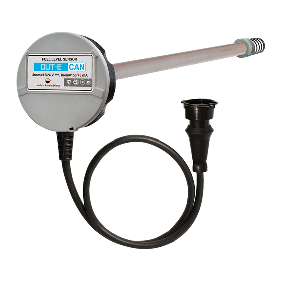
(see figure 7) consists of a measuring probe (1), fuel level sensor “head” with an electronic module located inside (2), interface cable (3) with connector for electrical connection (4). DUT-E AF DUT-E A5 DUT-E 232 DUT-E A10... - Page 16 DUT-E output signal specification according to Clauses 1.4.2 — 1.4.5. When using DUT-E AF/A5/A10/F/I fuel level sensors, calculation of fuel amount is carried out in a registration unit such as a GPS Tracking device or on the server using vehicle monitoring system software.
-
Page 17: Technical Specifications
0.6 (at L=1000 mm) Weight, kg, not more than 0.5 (at L=700 mm) 0.4 (at L=350 mm) figure 8 Overall dimensions, mm, not more than * For DUT-E CAN. DUT-E fuel level sensors. Operation manual. Version 8.1 © Technoton, 2020... -
Page 18: Specifications Of Dut-E Af Output Signal
General information and technical specifications of DUT-E / Technical specifications / Specifications of DUT-E AF output signal 1.4.2 Specifications of DUT-E AF output signal DUT-E AF fuel level sensor has an analog and frequency output which can be configured via K-Line (ISO 14230) interface. -
Page 19: Specifications Of Dut-E A5/A10/F/I Output Signal
Empty DUT-E A5 Full Empty DUT-E A10 Full Empty DUT-E F Full 1500 Empty DUT-E I 20.0 16.4 Full DUT-E fuel level sensors. Operation manual. Version 8.1 © Technoton, 2020... -
Page 20: Specifications Of Dut-E 232/485 Output Signal
DUT-E sensor sends data on current temperature as well (value is measured with the temperature sensor located on the PCB). DUT-E 232 and DUT-E 485 data transfer is carried out according to DUT-E COM Protocol. DUT-E fuel level sensors. Operation manual. Version 8.1 © Technoton, 2020... -
Page 21: Specifications Of Dut-E Can Output Signal
Fuel level and fuel volume in the tank PGN 62995 Unit passport PGN 63008 Unit state PGN 65226 Active DTC PGN 65276 Dash display PGN 65279 Operator indicators * See annex C for detailed description. DUT-E fuel level sensors. Operation manual. Version 8.1 © Technoton, 2020... -
Page 22: Dut-E And Tracking Devices Compatibility
Terminals of different models. table containing the up-to-date list of Declarations of compatibility of Telematics terminals from different manufacturers with products manufactured by Technoton is provided at: https://www.jv-technoton.com/. Recommendations on the equipment connection and configuration can be received at the... -
Page 23: Overall Dimensions
General information and technical specifications of DUT-E / Technical specifications / Overall dimensions 1.4.7 Overall dimensions Figure 8 — DUT-E overall dimensions * Nominal measuring probe length (350 mm/700 mm/1000 mm, see figure DUT-E fuel level sensors. Operation manual. Version 8.1 © Technoton, 2020... -
Page 24: Dut-E Installation
Contact the product supplier if there any defects. * Study carefully the layout of the mounting bores for a factory mounted fuel sensor and compare it with the drawing of bores for a DUT-E mounting plate. DUT-E fuel level sensors. Operation manual. Version 8.1 © Technoton, 2020... -
Page 25: Standard Fuel Sensor Replacement
(see figure 9). Figure 9 — Mounting plate screwed to the tank Preorder correspondent mounting plate to replace the standard sensor with SAE 5 bolt bores layout. DUT-E fuel level sensors. Operation manual. Version 8.1 © Technoton, 2020... -
Page 26: Installation Into A Special Hole
The mounting plate can be installed only in one position on the bores prepared! Before marking and drilling, examine the place where you plan to fix the mounting plate because sealing holes should be accessible. DUT-E fuel level sensors. Operation manual. Version 8.1 © Technoton, 2020... - Page 27 * Recommend for installation of sensor in fuel tank with thin walls (less than 2 mm). Figure 12 — Mounting plate fastening When using threaded rivets, they should be mounted using riveter and according to figure 13. DUT-E fuel level sensors. Operation manual. Version 8.1 © Technoton, 2020...
- Page 28 When fixing the mounting plate to the tank, make sure that the bolt or screw heads are not skewed and completely sunk in the plate in order to provide electrical isolation between the tank and DUT-E. DUT-E fuel level sensors. Operation manual. Version 8.1 © Technoton, 2020...
-
Page 29: Probe Cutting According To Tank Depth
Cut DUT-E probe with a metal hacksaw. Carefully clean the edge and wash the tubes with clean fuel (see figure 14). 3) After cutting the measuring probe of DUT-E AF/232/485/CAN models, you need to carry out the sensor calibration using Service DUT-E service software (see 3.10.3). -
Page 30: Length Extension
250, KDC 1000 with lengths of 250, 500 and 1000 mm respectively. After length extension the measuring probe of DUT-E AF/232/485/CAN models, you need to carry out the sensor calibration using Service DUT-E service software (see 3.10.3). DUT-E fuel level sensors. Operation manual. Version 8.1... -
Page 31: Mounting
DUT-E mounting. The mounting should be carried out so that both sensor and mounting plate sealing holes would match one another after locking the DUT-E. Figure 16 — DUT-E mounting DUT-E fuel level sensors. Operation manual. Version 8.1 © Technoton, 2020... -
Page 32: Electrical Connection
6) Quick splice connectors (ordered separately) are recommended for electrical connection of power supply wires (see figure 17 c). a) DUT-E to onboard electrical network scheme of connection Tie-wraps DUT-E signal cable b) connection cable laying DUT-E fuel level sensors. Operation manual. Version 8.1 © Technoton, 2020... - Page 33 Ground “-” (brown wire of the connection cable). Electrical isolation between the DUT-E body and the fuel tank is provided by the mounting plate made of dielectric plastic material. DUT-E fuel level sensors. Operation manual. Version 8.1 © Technoton, 2020...
-
Page 34: Electrical Connection Of Dut-E Af
DUT-E installation / Electrical connection / Electrical connection of DUT-E AF 2.7.1 Electrical connection of DUT-E AF DUT-E AF electrical connection is made according to pinout of the connector and interface cable wires description. See figure 18 and table 4 for details. -
Page 35: Electrical Connection Of Dut-E A5/A10/F/I
Assignment Pin number Wire color* marking T701/T034 White Output signal, see 1.4.3 GND/T734 Brown Ground “-” VBAT Orange Power supply “+” Manufacturer reserves the right to modify wire colors DUT-E fuel level sensors. Operation manual. Version 8.1 © Technoton, 2020... -
Page 36: Electrical Connection Of Dut-E 232/485
Power supply “+” Brown Ground “-” Received data (RS-232) 232R/485A White Data exchange (RS-485) Transmitted data (RS-232) 232T/485B Data exchange (RS-485) Manufacturer reserves the right to modify wire colors DUT-E fuel level sensors. Operation manual. Version 8.1 © Technoton, 2020... -
Page 37: Electrical Connection Of Dut-E Can
CAN-High (SAE J1939) CANL White CAN-Low (SAE J1939) KLIN Black K-Line (ISO 14230) Manufacturer reserves the right to modify wire colors RECOMMENDATION: Primarily check wire marking when connecting DUT-E sensors. DUT-E fuel level sensors. Operation manual. Version 8.1 © Technoton, 2020... -
Page 38: Monitoring Of Two And More Tanks
If there are three or more fuel tanks to be measured with DUT-E 232 sensors, cascade connection can be used according to figure 23 b. Quick splice connectors (ordered separately) are recommended for electrical connection of signal wires. DUT-E fuel level sensors. Operation manual. Version 8.1 © Technoton, 2020... - Page 39 ASCII EXT, Message Interval (s) set any required by the tracking device value (Operation modes module). Note — for sensor N (the last one) at least 8 second message interval is recommended. DUT-E fuel level sensors. Operation manual. Version 8.1 © Technoton, 2020...
- Page 40 DUT-E installation / Monitoring of two and more tanks / DUT-E 232 readings totalizing Figure 23 — DUT-E SUM 232 connection schemes DUT-E fuel level sensors. Operation manual. Version 8.1 © Technoton, 2020...
-
Page 41: Dut-E Af Readings Totalizing
DUT-E AF sensors are connected to the single tracking device according to figure 25 a. If there are three or more fuel tanks to be measured with DUT-E AF sensors, cascade connection can be used according to figure 25 b. - Page 42 DUT-E installation / Monitoring of two and more tanks / DUT-E AF readings totalizing Figure 25 — DUT-E SUM AF connection schemes DUT-E fuel level sensors. Operation manual. Version 8.1 © Technoton, 2020...
- Page 43 DUT-E installation / Monitoring of two and more tanks / DUT-E AF readings totalizing Table 9 — DUT-E SUM AF wires assignment Wire number Wire marking Wire color* Assignment VBAT Orange Power supply “+” Brown Ground KLIN Black K-Line (ISO 14230)
-
Page 44: Dut-E Can Readings Totalizing
DUT-E CAN. Summerized data of fuel volume (PGN 62982, see annex C) are provided only by the sensor which is assigned Master status. DUT-E fuel level sensors. Operation manual. Version 8.1 © Technoton, 2020... -
Page 45: Sealing
(see figure 26). Seals and cord are included into DUT-E delivery set. ATTENTION: Security sealing of DUT-E AF, DUT-E 232, DUT-E 485 and DUT-E CAN cable connector should be carried out after the configuration and calibration are finished (see 3) To seal the sensor put the sealing cord through the special holes of the mounting plate and DUT-E body. -
Page 46: Configuration Of Sensor Using Service Adapter
Configuration of sensor using service adapter / SK DUT-E purpose of use 3 Configuration of sensor using service adapter Minimum/maximum measurement level calibration is required for correct operation of DUT-E AF/232/485/CAN as well as configuration according to specific operating conditions and requirements of tracking devices/data loggers. ATTENTION: DUT-E A5/A10/F/I do not require any calibration and configuration. -
Page 47: Hardware Requirements
CPU — Intel Core i3, dual-core, 2.0 GHz; • RAM — 4 Gb; • availability of USB 2.0 port; • display resolution 1366x768. ATTENTION: Service adapter operation is possible only after preliminary installation driver. DUT-E fuel level sensors. Operation manual. Version 8.1 © Technoton, 2020... -
Page 48: Service Adapter Components
- SK DUT-E specification; - USB A-B cable; - CAN service cable; - RS-485 service cable; - RS-232 service cable; - AF service cable. Figure 27 — SK DUT-E delivery set DUT-E fuel level sensors. Operation manual. Version 8.1 © Technoton, 2020... -
Page 49: Universal Service Adapter
3 – RX green LED indicator of data received from DUT-E; 4 – ON red LED indicator of power supply; 5 – USB B port for PC connection. Figure 28 — Adapter exterior view DUT-E fuel level sensors. Operation manual. Version 8.1 © Technoton, 2020... -
Page 50: Usb A-B Cable
3.3.3 USB A-B Cable USB A-B cable is used for connection of PC and adapter (see figure 29) USB A USB B Figure 29 — USB A-B cable connectors DUT-E fuel level sensors. Operation manual. Version 8.1 © Technoton, 2020... -
Page 51: Service Cable
Received 485A White RS-485 data interface Analog, Power VBAT Orange voltage supply 0…50 V Brown Ground Serial, Received RS-485 485A White data interface Serial, Transmitted 485B RS-485 data interface DUT-E fuel level sensors. Operation manual. Version 8.1 © Technoton, 2020... -
Page 52: Service Cable
VBAT Orange voltage supply 0…50 V Analog, Power VBAT Orange voltage supply 0…50 V Brown Ground Serial, Received 232R White RS-232 data interface Serial, Transmitted 232T RS-232 data interface DUT-E fuel level sensors. Operation manual. Version 8.1 © Technoton, 2020... -
Page 53: Af Service Cable
Configuration of sensor using service adapter / Service adapter components / AF service cable 3.3.6 AF service cable AF service cable used to connect adapter to DUT-E AF. Table 12 — Pinout of AF service cable connectors Wire Signal View... -
Page 54: Can Service Cable
Discrete selection Analog, Power VBAT Orange voltage supply 0…32 V Brown Ground Analog, Power VBAT Orange voltage supply 0…32 V Brown Ground Serial, KLIN Black K-Line ISO 14230 standard DUT-E fuel level sensors. Operation manual. Version 8.1 © Technoton, 2020... -
Page 55: Software Installation
3) After accepting User License Agreement (see figure 16) the installation process will be continued. During installation, please follow the instructions of Bridge Driver Installer. Figure 31 — Acceptance of the License agreement and successful installation notification USB driver window DUT-E fuel level sensors. Operation manual. Version 8.1 © Technoton, 2020... -
Page 56: Service Dut-E Software Installation
The following window will indicate the process of installation of Service DUT-E files. Since the installation of Service DUT-E software is finished PC is ready for service adapter connection and operation (see figure 34). Figure 34 — Service DUT-E installation progress DUT-E fuel level sensors. Operation manual. Version 8.1 © Technoton, 2020... -
Page 57: Service Adapter Connection
• visible damages of the adapter body; • connector and insulation damages of cables. Contact the supplier if any defects detected. DUT-E fuel level sensors. Operation manual. Version 8.1 © Technoton, 2020... -
Page 58: Operation Restrictions
To avoid any service adapter faults in communication between PC and sensor make sure there are no sources of electromagnetic interference close to the workplace (running electric motors, welding equipment, high-power transformers, power lines, etc.). DUT-E fuel level sensors. Operation manual. Version 8.1 © Technoton, 2020... -
Page 59: Connecting Dut-E To Pc
1 While configuring DUT-E 232/485 it is power-supplied through USB A-B cable from USB-port. 2 While configuring DUT-E AF/CAN power supply should be additionally connected from accumulator battery or other power source. • while configuring DUT-E CAN connected by S6 Technology, the connector of service cable from S6 SK (see figure 36 b) or SK DUT-E (see figure 35 c) should be connected to any free S6 connector. - Page 60 Configuration of sensor using service adapter / Service adapter connection / Connecting DUT-E to PC a) DUT-E AF connection b) DUT-E CAN connection c) DUT-E CAN connection via S6 Technology For connecting power supply (battery) you can choose any of marked places.
- Page 61 Figure 36 — DUT-E to PC connection schemes while using S6 SK For connecting power supply (battery) you can choose any of marked places. ** No need to connect. Power supply (battery) is carried out though S6 cabling system. DUT-E fuel level sensors. Operation manual. Version 8.1 © Technoton, 2020...
-
Page 62: Operation Test
Green DUT-E data is being received No signal No data from DUT-E Yellow Data is being transmitted to DUT-E No signal No data to DUT-E DUT-E fuel level sensors. Operation manual. Version 8.1 © Technoton, 2020... -
Page 63: Software Launch
RS-232, RS-485 or K-line connection (see figure 39). LED indicators of the adapter will display signals according to table 14. Figure 39 — Service DUT-E main window with sensor connection established DUT-E fuel level sensors. Operation manual. Version 8.1 © Technoton, 2020... -
Page 64: User Interface And Initial Setup
Information and configuration area at the right side of the window. Vertical menu also contains Diagnostics and Fuel tank calibration entries. The only initial setting required is selection of user interface language. DUT-E fuel level sensors. Operation manual. Version 8.1 © Technoton, 2020... -
Page 65: Operations With Dut-E Profile
Profile of the connected DUT-E sensor is loaded when From sensor option is selected. ATTENTION: File extension of DUT-E profile is *.dpf DUT-E fuel level sensors. Operation manual. Version 8.1 © Technoton, 2020... -
Page 66: Save Profile
(see figure 43). Figure 43 — Password request Note — default password for DUT-E sensors is 1111. It is stated in sensor specification in factory settings list. DUT-E fuel level sensors. Operation manual. Version 8.1 © Technoton, 2020... -
Page 67: Print Profile
E DUT-E profile printed copy example. RECOMMENDATION: It is recommended to attach profile hard copy to sensors Specification for further tracking of setting modifications made for particular sensor. DUT-E fuel level sensors. Operation manual. Version 8.1 © Technoton, 2020... -
Page 68: Vertical Menu Description
• firmware version. This data cannot be edited by the user. Serial number and firmware version is also displayed at connection status area of the window. Figure 44 — Passport module DUT-E fuel level sensors. Operation manual. Version 8.1 © Technoton, 2020... -
Page 69: Authorization
To set new password enter current password, tick new password box, enter new password and click button (see figure 46). a) entering new password b) confirmation of successful password modification Figure 46 — Setting new password DUT-E fuel level sensors. Operation manual. Version 8.1 © Technoton, 2020... - Page 70 ATTENTION: Contact Technoton technical support at support@technoton.by if the password is lost. Requirements for password recovery request: • scan copy of the request signed and sealed by the official representative of the company the sensor been purchased by should be attached;...
-
Page 71: Settings - Calibration
8) Wait for 3…5 seconds for sensor readings stabilization. 9) Click for maximum level calibration. 10) Min/max calibration is finished. Drain hole a) measuring probe length b) Settings-Calibration entry Figure 48 — DUT-E min/max calibration DUT-E fuel level sensors. Operation manual. Version 8.1 © Technoton, 2020... -
Page 72: Settings - Operation Modes
Configuration of sensor using service adapter / Vertical menu description / Settings - Operation modes 3.10.4 Settings – Operation modes Operation modes entry contains settings to configure sensor for operation in particular conditions with compliance of tracking device requirements (see figure 49). a) DUT-E AF b) DUT-E CAN c) DUT-E 232/485 d) Automatic transmission... - Page 73 • Master - should be selected for a sensor which has the highest decimal address in the network; • Slave - should be selected for all the other network sensors. Only for DUT-E 232/485. Only for DUT-E AF/CAN/485. Only for DUT-E CAN. DUT-E fuel level sensors. Operation manual. Version 8.1 © Technoton, 2020...
-
Page 74: Settings - Thermal Compensation
- There should be the same fuel volume in the tank (refueling or draining is not allowed) a) disabling the feature b) inserting coefficient Figure 50 — Thermal compensation setting DUT-E fuel level sensors. Operation manual. Version 8.1 © Technoton, 2020... -
Page 75: Settings - Output Message
• fuel volume in liters (L), 0.1 l step; • fuel volume in percentage (%), 0.4 % step. Figure 51 — Selection of output value type for DUT-E 232/485 DUT-E fuel level sensors. Operation manual. Version 8.1 © Technoton, 2020... -
Page 76: Settings - Calibration Table
(Level (mm) field) and fuel volume in the tank (Volume (l) field). Recommended number of table entries is 15. Max possible is 30 entries (see figure 52). Figure 52 — Calibration table DUT-E fuel level sensors. Operation manual. Version 8.1 © Technoton, 2020... - Page 77 While creating the calibration table, we recommend to enter for its first point (level of 0.0 mm) the value of the fuel volume which is equal to the volume of not consumed fuel remaining in the tank. DUT-E fuel level sensors. Operation manual. Version 8.1 © Technoton, 2020...
-
Page 78: Settings - Interface
Interface module (see figure 53) provides selection of baud rate for RS-232 (for DUT-E 232), RS-485 (for DUT-E 485) and K-line (for DUT-E CAN/AF) connections out of drop-down list: • 4800 bit/s; • 9600 bit/s; • 19200 bit/s. Figure 53 — Interface setting DUT-E fuel level sensors. Operation manual. Version 8.1 © Technoton, 2020... -
Page 79: Settings - Analog Output
Configuration of sensor using service adapter / Vertical menu description / Settings – Analog output 3.10.9 Settings – Analog output Analog output* module of Service DUT-E used for configuration of DUT-E AF output voltage range according to the voltage range of the tracking device input (see figure 54). - Page 80 On — for U mode 0.5 V and 9.5 V voltage are diagnostics values according to table For F mode 400 Hz and 1600 Hz frequency are diagnostics values according to table • Off — special diagnostics output values are disabled. Default setting. DUT-E fuel level sensors. Operation manual. Version 8.1 © Technoton, 2020...
-
Page 81: Diagnostics
Recorded log files (*.txt) are automatically stored to \DUT_LOG folder of the software installation directory on PC. File name consists of sensor serial number, date and time of log start. annex F for a log file example. DUT-E fuel level sensors. Operation manual. Version 8.1 © Technoton, 2020... - Page 82 (or) — 134 (-122)* recalibrate the sensor** * Different malfunction code display. ** Fuel tank calibration table should be recompiled and recorded all over again into sensor internal memory. DUT-E fuel level sensors. Operation manual. Version 8.1 © Technoton, 2020...
-
Page 83: Firmware Update
Before the end of the update process it is forbidden to 1) Disconnect DUT-E from the adapter. 2) Disconnect adapter from the PC. 3) Power down the PC. 4) Run any resource-intensive applications on the PC. DUT-E fuel level sensors. Operation manual. Version 8.1 © Technoton, 2020... - Page 84 Service DUT-E will display the new firmware version at Connection status area in case the update is successful. DUT-E is ready for further operation. In case of any error occur check all the cable and adapter connections and retry. Contact Technoton technical support support@technoton.by if another try is also unsuccessful.
-
Page 85: Software Shutdown And Dut-E Disconnection
Disconnect DUT-E service cable from the sensor connector. Adapter can now be used for the next sensor connection (see 3.5.3). * This step is only applied for DUT-E CAN/AF. DUT-E fuel level sensors. Operation manual. Version 8.1 © Technoton, 2020... -
Page 86: Measurement Accuracy Check
Calibrated measuring containers must be used to determine the exact amount of drained/refilled fuel. ATTENTION: The amount of any fuel filling/draining during the accuracy test should not be less than 20 % of total tank capacity. DUT-E fuel level sensors. Operation manual. Version 8.1 © Technoton, 2020... -
Page 87: Check Tests Procedure
When analyzing accuracy errors, "Drain" and "Refill" parameters are estimated as a percentage relative to the total tank capacity. annex A for check test report template and error calculation formula. DUT-E fuel level sensors. Operation manual. Version 8.1 © Technoton, 2020... -
Page 88: Accessories
* 1 pc. – used for DUT-E installation and 1 pc. is a spare part. Could be complemented with 4 mm thick gasket. ** Exterior of seal can be different. DUT-E fuel level sensors. Operation manual. Version 8.1 © Technoton, 2020... -
Page 89: Adapter Unit
To enable the fuel gauge working with DUT-E US-1 adapter unit is used (see figure 61) ATTENTION: Adapter unit can only operate with DUT-E A5 or DUT-E AF with 1.5…4.5 V configured output signal. Table 18 — Adapter unit modifications... -
Page 90: Screen Filter
(see figure 62 b). Screen filter a) mounting location Fixator Bottom-stop b) mounting order Figure 62 — Screen filter ATTENTION: Screen filter cannot be used without installed bottom spring stop. DUT-E fuel level sensors. Operation manual. Version 8.1 © Technoton, 2020... -
Page 91: Connection Cables
(232/485 cable DUT-E-232/485. extender) Length – 10 m S6 SC-CW-700 To connect DUT-E CAN sensors to (cable) recording and display units and to external power supply. Length – 7 m DUT-E fuel level sensors. Operation manual. Version 8.1 © Technoton, 2020... -
Page 92: Additional Accessories
Special duralumin DUT-E TAM-d105 Mounting plate mounting plate for 6 screws Fastening plate for sensors installation Wedge-shaped DUT-E WP-10 on fuel tanks with fastening plate inclined surface (10-degree angle) DUT-E fuel level sensors. Operation manual. Version 8.1 © Technoton, 2020... -
Page 93: Diagnostics And Troubleshooting
2 mA (for DUT-E I) * Only for DUT-E AF Diagnostics of DUT-E AF can be carried out with service adapter the same way as for other DUT-E modifications having digital output (see 6.3). DUT-E fuel level sensors. Operation manual. Version 8.1... -
Page 94: Dut-E With Frequency Output
Sensor PCB failure Contact the closest service center Diagnostics of DUT-E AF can be carried out with service adapter the same way as for other DUT-E modifications having digital output (see 6.3). DUT-E fuel level sensors. Operation manual. Version 8.1... -
Page 95: Dut-E With Digital Output
Diagnostics and troubleshooting / DUT-E with digital output 6.3 DUT-E with digital output Normal operation of digital DUT-E sensors is verified with the help of service adapter connection (see 3.10.10). DUT-E fuel level sensors. Operation manual. Version 8.1 © Technoton, 2020... -
Page 96: Maintenance
Centers (hereinafter, RSCs). Full RSCs list can be found at https://www.jv-technoton.com/. * DUT-E AF/232/485/CAN models. Repeated calibration of sensor for minimum and maximum values for DUT-E A5/A10/F/I is done only by RSC. DUT-E fuel level sensors. Operation manual. Version 8.1... -
Page 97: Demounting
1) To avoid any cable/PCB damage do not pull the interface cable when demounting DUT-E. 2) In case of repeated installation of DUT-E – replace the old rubber gasket with a new one. DUT-E fuel level sensors. Operation manual. Version 8.1 © Technoton, 2020... -
Page 98: Examination
• damage of the plastic mounting plate and traces of fuel leaks through the rubber gasket of the mounting plate. Contact (see 7.1) or Manufacturer if the defects detected. DUT-E fuel level sensors. Operation manual. Version 8.1 © Technoton, 2020... -
Page 99: Cleaning
To clean the tubes wash them with the clean fuel. It is also recommended to wash the screen filter as well. ATTENTION: Avoid fuel getting on DUT-E head body, interface cable and its connector when washing the tubes. DUT-E fuel level sensors. Operation manual. Version 8.1 © Technoton, 2020... -
Page 100: Packaging
SK DUT-E box. (see figure 64 b). a) DUT-E b) SK DUT-E Figure 64 — Packaging label Note — label design and contents can be modified by the Manufacturer. DUT-E fuel level sensors. Operation manual. Version 8.1 © Technoton, 2020... -
Page 101: Storage
100 % at +25° C. Do not store DUT-E in the same room with substances that cause metal corrosion and/or contain aggressive impurities. DUT-E shelf life must not exceed 24 months. DUT-E fuel level sensors. Operation manual. Version 8.1 © Technoton, 2020... -
Page 102: Transportation
When transporting by air, DUT-E must be stored in heated pressurized compartments. Air environment in transportation compartments should not contain acid, alkaline and other aggressive impurities. Shipping containers with packed DUT-E sensors should be sealed. DUT-E fuel level sensors. Operation manual. Version 8.1 © Technoton, 2020... -
Page 103: Utilization/Re-Cycling
DUT-E does not contain precious metals in amount that should be recorded. DUT-E fuel level sensors. Operation manual. Version 8.1 © Technoton, 2020... -
Page 104: Contacts
Contacts Contacts Distribution, technical support and service Tel/fax: +375 17 240-39-73 marketing@technoton.by support@technoton.by Manufacturer Zavod Flometr Tel/fax: +375 1771 3-29-21 office@flowmeter.by DUT-E fuel level sensors. Operation manual. Version 8.1 © Technoton, 2020... -
Page 105: Annex A Template Of Check Test Report
The results of measurement match/do not match specifications. The results of refueling measurement match/do not match specifications. Comments: _________________________________________________________ representative of the CUSTOMER: __________________/____________________/ representative of the CONTRACTOR: __________________/__________________/ DUT-E fuel level sensors. Operation manual. Version 8.1 © Technoton, 2020... -
Page 106: Annex B Examples Of Dut-E Can Connection
Figure B.1 — Connecting one DUT-E CAN to the Telematics terminal which is incompatible with S6 cable system Figure B.2 — Connecting several DUT-E CAN to the Telematics terminal which is incompatible with S6 cable system DUT-E fuel level sensors. Operation manual. Version 8.1 © Technoton, 2020... - Page 107 Figure B.3 — Connecting one DUT-E CAN to the Telematics terminal which is compatible with S6 cable system Figure B.4 — Connecting several DUT-E CAN to the Telematics terminal which is compatible with S6 cable system DUT-E fuel level sensors. Operation manual. Version 8.1 © Technoton, 2020...
-
Page 108: Annex C Messages Of Dut-E Can Data Transfer Protocol
Settings version 521124 8 bytes DUT-E CAN Production date 521125 4 bytes DUT-E CAN DUT-E CAN address in the 521188 1 byte CAN bus — the bytes are not used. DUT-E fuel level sensors. Operation manual. Version 8.1 © Technoton, 2020... - Page 109 Status GPS/GLONASS Antenna 2 bytes 521135 Status 2 bytes Modem Power Status 521130 2 bytes Modem Registration Status 521131 1 byte Reserved_8 524000 — the bytes are not used. DUT-E fuel level sensors. Operation manual. Version 8.1 © Technoton, 2020...
- Page 110 2 bits Operator Shift Prompt 5675 3 bits Driver Warning System 5825 Indicator Status 3 bits Emission Control System 5826 Operator Inducement Severity — the bytes are not used. DUT-E fuel level sensors. Operation manual. Version 8.1 © Technoton, 2020...
- Page 111 (the difference is more than 100 Hz) * Fuel tank calibration table should be recompiled and recorded all over again into sensor internal memory. DUT-E fuel level sensors. Operation manual. Version 8.1 © Technoton, 2020...
-
Page 112: Annex D Example Of Dut-E Can Connection Via Rs-232 Interface
Figure D.1 — Connection of several DUT-E CAN to the Telematics terminal for summarization of readings via RS-232 interface DUT-E fuel level sensors. Operation manual. Version 8.1 © Technoton, 2020... -
Page 113: Annex E Dut-E Profile Printed Copy
Annex E DUT-E profile printed copy Annex E DUT-E profile printed copy Fuel level sensor Passport Model sensor DUT-E AF Serial number 092001302783 Firmware version 3.12 Date compil Jan 09 2016 Time compil 09:15:05 Settings Calibration Actual length of sensor after trimming (mm) 685.0... -
Page 114: Annex F Dut-E Log File Example
— fuel level (s.u.); — initial fuel level (mm); — temperature compensated fuel level (mm); — temperature compensated filtered fuel level (mm); — fuel volume (l); — fuel volume (%). DUT-E fuel level sensors. Operation manual. Version 8.1 © Technoton, 2020... -
Page 115: Annex G Electromagnetic Compatibility Specifications Of Dut-E
Tested bandwidth, interference, dB µV/m interference, dB µV/m Horizontal Vertical Horizontal Vertical polarization polarization polarization polarization 30…34 34…45 45…60 60…75 75…100 100…130 130…170 170…225 225…300 300…400 400…525 525…700 700…850 850…1000 DUT-E fuel level sensors. Operation manual. Version 8.1 © Technoton, 2020... -
Page 116: Annex H Videography
7) Video clip Filter Screen of DUT-E fuel level sensor Check out the link: https://www.youtube.com/watch?v=B5dcYxGfSqQ 8) Other Technoton videos are on the YouTube channel which is regularly updated: https://www.youtube.com/channel/UCq7EF3DHrgl7fOWB2ynsR-A DUT-E fuel level sensors. Operation manual. Version 8.1 © Technoton, 2020...
Need help?
Do you have a question about the DUT-E AF and is the answer not in the manual?
Questions and answers