
Related Manuals for SPX Pearpoint P350 flexitrax

Summary of Contents for SPX Pearpoint P350 flexitrax
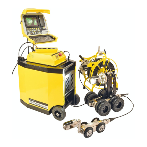
- Page 1 P350 flexitrax Pearpoint’s advanced crawler- based video inspection system Operation Manual Issue 5 July 2011 90/P350-OPMAN-ENG/05...
- Page 2 P350 flexitrax system ™...
-
Page 3: Preface
Preface Before you begin Installation The P350 flexitrax, including its component parts is heavy. Please read this operation manual before attempting to If available, use the wheels to assist transport. Observe use the P350 flexitrax system. Note that this manual and heavy-lifting safety practices when lifting any component all its contents are subject to change. -
Page 4: Operation Guidelines
Operation guidelines • When stopping the generator; ensure all electrical loads, including the P350 are switched off before Please observe your company, region or country’s stopping the generator. Standard Code of Practice for surveying underground • Starting or stopping a generator whilst the P350 utilities with CCTV equipment, if applicable, when using system is connected and the main switch is in the this equipment. - Page 5 P350 flexitrax Operation Manual iii...
-
Page 6: Compliance
Radiodetection is a subsidiary of SPX Corporation. SPX, Radiodetection and flexitrax are trademarks of Industry Canada compliance Radiodetection Ltd. and SPX Corporation. Due to a policy statements of continued development, we reserve the right to alter or amend any published specification without notice. -
Page 7: Table Of Contents
Table of contents Preface 3.1.5 Auxiliary Lighthead 3.1.6 Crawler connection Before you begin 3.2 Crawler deployment tools Important safety notices 3.3 Manual drum and external PSU Warnings, Cautions and Notes 3.4 Powered drum Key to symbols used 3.5 Command module General 3.5.1 Mounting Installation... - Page 8 6.3.6 Deleting files and folders Section 5 – System operation 6.3.7 Creating folders 5.1 Emergency stop 6.3.8 Sending a file with Bluetooth®: 5.2 Deployment 6.3.9 Information 5.2.1 Before deployment 6.4 Viewing Pitch Log 5.2.2 Using the crawler deployment tool 6.5 Viewing JPEG pictures 5.2.3 Cable and manhole rollers 6.6 Playing videos 5.2.4 Distance counter and Auto Stop point 6.6.1 Screen captures...
- Page 9 8.3.1 INPUT List of figures and tables 8.3.2 DESTN Figure 2.1: Command module 8.3.3 FNAME Figure 2.2: Command module rear view 8.4 Video playback Figure 2.3: Command module I/O panel 8.4.1 Command module playback Figure 2.4: Command module keypad 8.4.2 Computer playback Figure 2.5: Powered drum with command module 8.5 Distributing your recordings installed 8.5.1 Producing a DVD video...
- Page 10 Figure 5.3: Crawler grab setup Figure 9.7: Powered drum with slave side panel and drum support channel removed Figure 5.4: Crawler grab and crawler Figure 9.8: Adjusting the drive train Figure 5.5: Crawler grab and crawler with attached elevator Figure 9.9: Cable layering sprocket and follower Figure 5.6: Crawler grab in the closed position Figure 9.10: Cable layering mechanism Figure 5.7: Lowering the crawler into a manhole...
-
Page 11: Section 1 - Introduction
Section 1 – Introduction 1.1 About this manual 1.2 Overview This manual provides comprehensive operating The P350 flexitrax is an advanced pipeline video instructions for the P350 flexitrax pipeline video inspection system that is ideal for a broad range of ™... -
Page 12: Section 2 - System Overview
Section 2 – System overview 2.1 Command module RJ-45 socket: Connects to a PC running compatible reporting software. The command module acts as the controller and digital Optional Vehicle wall mount kit: to mount the video recorder and playback device. Video is displayed command module to the side of your van on an 8”... - Page 13 Figure 2.1: Command module Figure 2.3: Command module I/O panel Figure 2.2: Command module rear view Figure 2.4: Command module keypad P350 flexitrax Operation Manual 3...
-
Page 14: Cable Drums
2.2 Cable drums 2.2.2 Manual drum Cable drum: Houses up to 250m (820’) of cable. The system supports either a powered or manual drum that can accommodate cable lengths of 100m (330’), Cable brake. 150m (495’) or 250m (820’). The powered drum contains Crawler connection terminal (Not shown). - Page 15 Figure 2.5: Powered drum with command module installed Figure 2.7: Front and rear connection panels (Common to powered drum and external PSU) Figure 2.6: Manual drum Figure 2.8: External PSU Figure 2.9: Link cables P350 flexitrax Operation Manual 5...
-
Page 16: Crawlers And Crawler Cameras
2.3 Crawlers and Crawler cameras Figure 2.10: P354 crawler with P350-CAM-FW camera installed The system offers two different crawlers: the P354 (100mm/4”) and P356 (150mm/6”). Both crawlers are fully compatible with three interchangeable cameras. The P350-CAM-FW is a fixed, forward view camera. The P350-CAM-PT offers pan and tilt capabilities and the P350-CAM-PTZ offers pan, tilt and 10x optical zoom. -
Page 17: Section 3 - System Assembly
Section 3 – System assembly 3.1.1 Crawler weight (P354 Only) The P350 flexitrax allows you to configure the system in a large number of ways, depending on the The crawler weight is a metal plate designed to increase components you have chosen for your survey. This traction on the P354 crawler by adding more weight to section provides details on assembling and setting up the crawler’s body. -
Page 18: Wheels And Tires
3.1.2 Wheels and tires For a complete list of compatible wheels and tires, please visit www.radiodetection.com. The P354 is compatible with the 62mm (2.5”) and 110mm Figure 3.3 (opposite) shows a range of recommended (4.3”) wheel sets, which can be connected in singular wheel and elevator configurations to suit a variety of or twin configurations. - Page 19 P350 flexitrax Operation Manual 9...
-
Page 20: Cameras
3.1.3 Cameras Pan and Tilt cameras P350-CAM-PT (Figure 3.6): the pan and tilt capabilities The P354 and P356 are compatible with three high- provides the crawler with almost 360° vision. The pan resolution cameras that support PAL or NTSC video and tilt camera’s focal range is from 10mm to infinity;... -
Page 21: Auxiliary Lighthead
• P350-ELV-LAM large adjustable elevator (P356 only) Figure 3.10: Installing the large adjustable elevator (Figure 3.8 right). The large adjustable elevator will deploy the P356 in pipes from up to 600mm (24"). Figure 3.8: P350 camera elevators Adjustable elevator To adjust the P350-ELV-A elevator: Figure 3.11: Adjusting the large adjustable elevator Loosen the Allen-head and the vent screws (Figure 3.9) -
Page 22: Crawler Connection
3.2 Crawler deployment tools 3.1.6 Crawler connection Once you have fitted the crawler with the cameras, The crawler deployment grab tools for the P354 and wheels and other accessories, you can connect it to the P356 crawlers are optional accessories that allow an cable drum. -
Page 23: Manual Drum And External Psu
3.3 Manual drum and external PSU 3.5.3 Compact Flash card Insert a high quality Compact Flash card into the card The manual drum (Figure 2.6) is a light-weight system slot, which is located inside the Command Module’s I/O that can house up to 250m of cable. The external PSU panel (Item 10 in Figure 2.3). -
Page 24: Section 4 - Commcommand Module Command System Setup
Section 4 – Command module and system setup 4.3 Getting help This section introduces the P350 command module and system setup. The command module has a built in, context sensitive help screen. To access the help page, press Fn + F1 4.1 Overview simultaneously on the keypad or Shift + F1 on the keyboard. -
Page 25: On-Screen Display (Osd)
• Company as defined in the Company Details menu Figure 4.2 System onscreen display (OSD) (see Section 4.10). • Crew as defined in the Company Details menu Mode Status Time Date Counter (See section 4.10). To clear the welcome screen, press OK on the keypad. ... -
Page 26: System Menu Timeout
Figure 4.5: Custom OSD layout Normal layout: This is the standard layout optimised to make use of the entire screen (See Figure 4.3). OSD information fields and overlaid text are positioned at the very edges of the display. Figure 4.3: Normal OSD layout CAUTION: Be careful not to overlap the OSD fields as this will affect their readability on the screen and in recordings. -
Page 27: Text Appearance
Press MENU. Figure 4.6: Main screen showing top-level system menu keys to select the desired mode. Menu timeout on: If selected the system menu will disappear after 20 seconds. Press any function keys to make it visible again. Menu timeout off: If selected the system menu will be constantly visible on the screen. -
Page 28: Setup Menu
4.6.2 SETUP menu Entering text with the keypad The SETUP menu provides access to all configuration You can enter text with the keypad arrows. settings on the command module and most connected Use the arrows to cycle through the list components. Table 4.1 provides a comprehensive of available characters. - Page 29 – PREV Previous setting. – RESET Reset to automatic mode. – PIPE Optimize camera for pipe conditions. – SURF Optimize camera for surface conditions. – ULOAD Upgrade camera software. – INFO Display camera software version. On Screen Display menu. – L’OUT On Screen Display Layout menu –...
-
Page 30: Card Menu
– REMOV Remove current logo. – COMPANY Company name. – CREW Crew name. – STREET Company address. – CITY City. – POSTCODE Post or Zip code. – PHONE Telephone number. – Fax number. – EMAIL Email. RSTOR Factory reset menu. –... - Page 31 Table 4.3: DVR menu schema Menu Description INPUT Input source menu. – Auto Select the devices connected at startup giving preference to a P350 camera. – External Select an external device. – Camera Select a P350 camera. DESTN Destination folder menu. –...
-
Page 32: Scrn Menu
4.6.5 SCRN menu The SCRN menu allows you to set brightness and contrast of the command module’s LCD. Table 4.4 provides a comprehensive description of the SCRN menu. Table 4.4 Screen menu schema Menu Description Set brightness level. CONTR Set contrast level. 4.6.6 DRIVE The DRIVE menu allows you to drive a crawler and set driving preferences. -
Page 33: Text And Report Menu
– 640Hz Select 640Hz transmission frequency. – 8192Hz Select 8192Hz transmission frequency. – 32768Hz Select 32768Hz transmission frequency. – OSD menu. – MIMIC Mimic menu. – OnOff Hide or display mimic. – POSITION Set mimic’s position on screen. – COLOR Set mimic’s color. -
Page 34: Command Module Settings
4.7 Command module settings Pushrod reels Once the system is correctly assembled, you must • Reel: Rod P341 Plumbers 30m (100’). configure it for the first time before you begin your pipe • Reel: Rod P341 Plumbers 60m (100’). inspection. To set the command module’s basic settings •... -
Page 35: Camera Settings
4.9.3 Camera settings Logo The camera settings menu allows you to adjust the Your company logo. To enter it copy a JPEG version of camera’s white balance and operating mode. To change your company logo (32KB maximum) into the root of a camera settings go to DRIVE->SETUP->CAM and select compact flash card and insert it in the command module. -
Page 36: Splash And Video Title Screens
Figure 4.8: Video title page Use this field to record your company’s fax number (20 char max). Email Use this field to record your company’s contact email address (30 char max). 4.11 Splash and video title screens The P350 flexitrax features several splash and information screens. -
Page 37: Restoring Factory Settings
To configure the ethernet port, go to SETUP -> COMMS -> ETH. See Figure 4.9. Figure 4.9: Ethernet configuration Status indicates if the P350 system is connected or not. Use the arrows to select a setting and press OK to edit it. Boot Type: Choose between DHCP and Static IP. -
Page 38: Section 5 - System Operation
Section 5 – System operation This section introduces the procedure for deploying the Pearpoint recommend the use of downhole (Figure 5.1) P350 flexitrax system and inspecting pipes and conduits. and manhole rollers as there is a risk of scoring or damaging cables during deployment and during a survey. - Page 39 Figure 5.3: Crawler grab setup Figure 5.4: Crawler grab and crawler Toggle Clamp Open position Connecting Bars Bowden cable clamping screws Holding screws Testing and Adjustments Assemble as many rods as are required by screwing them together. Without assembling the positioning rods, place the Attach the rods to the crawler grab.
-
Page 40: Cable And Manhole Rollers
Figure 5.5: Crawler grab and crawler with attached elevator Figure 5.7: Lowering the crawler into a manhole When the crawler reaches the bottom of the manhole, use a combination of the rope and rods to position the crawler in the desired orientation. When the crawler is positioned to your satisfaction, release the toggle clamp’s lever to disengage the crawler. -
Page 41: Distance Counter And Auto Stop Point
5.2.4 Distance counter and Auto Press OK to confirm the selection and exit to the previous menu. Stop point You can also use the shortcut Fn + F5 to activate or de- Once you have deployed and positioned the crawler in activate the sonde without having to enter the Sonde menu the manhole, using manhole rollers to protect the cable For more information on locating the sonde, please refer to the... - Page 42 If a valid application is missing on any of the components NOTE: If the system is set to interface to a push rod then the DRIVE menu will not be accessible and ROD as a result of a failed upload, a warning message will will be displayed in the MODE field of the OSD.
-
Page 43: Mimic
To reset the inclinometer: Steering mimic Press ZERO. The command module will prompt Steering mimic (Figure 5.11) is displayed when a P356 you to check that the crawler is level. crawler is connected to the system. In addition to the Press OK to reset the inclinometer or press features of the basic mimic, steering mimic features a CANCL to return the previous menu. -
Page 44: Navigating With Advanced Mimic
S key the camera will swivel 90° to the left (Figure 5.13.4). A note on automatic camera movements Likewise if you move the cursor to the 12 o’clock position When you use mimic to control the camera’s viewpoint, on the inner circle and press S the crawler will look 90° up the camera uses a series of calculations to determine (Figure 5.13.6). - Page 45 Figure 5.13: Advanced mimic controls P350 flexitrax Operation Manual 35...
-
Page 46: Manual System
5.3.6 Manual system Automatic mode NOTE: The P354 and P356 crawlers feature an In AUT mode the crawler will not move backwards until it automatic roll-over drive correction system: if they detects that the cable is being retrieved. Automatic mode roll-over for any reason the direction of movement will is recommended for most situations. -
Page 47: Steering (P356 Crawler Only)
The crank socket is located under the side panel closest Pressing subsequent times will increase the crawler to the controller socket. The panel is secured with socket- reverse speed incrementally. head screws. Remove this panel using a metric Allen key. Decrease the speed by holding or pressing . -
Page 48: Tractor Power
Whilst moving you can achieve a tighter turn by using the No camera control Check camera connector lock steer function. No video, no video at Drum Check tractor connector, In this mode one set of wheels will lock. This gives a tight check down-hole cable, turn, but will reduce the crawlers pulling power. -
Page 49: Still Pictures
5.5 Still pictures WARNING! The camera and lighthead LEDs are very powerful. Do not look directly at the LEDs or You can save a screenshot of what is shown on the point them at other people. screen at any time, even during recording or playback of a video. -
Page 50: Center
5.8 Pendant controller 5.6.6 Center When using the P350-CAM-PT and P350-CAM-PTZ The P350 pendant controller is an optional accessory you can return the camera to the forward view, leveled which allows the user to control the system remotely. position by pressing simultaneously. - Page 51 NOTE: Continuous pressing of either [+] or [-] key will Connections: result in ‘wrap around’ of camera focus i.e. in focus The P350 pendant lead connects to the pendant – out of focus – in focus. controller socket (item 7 in fig 2.7) on the powered drum IRIS or manual PSU.
- Page 52 SCAN SONDE Pressing the [SCAN] key will cause the camera to centre Pressing the [SELECT] key will disable the sonde and itself, pan 90° and roll through 360° to scan the periphery cycle through the four available sonde frequencies. of the image. The scan can only commence if the green Sonde frequency is shown on the adjacent indicator pair.
-
Page 53: Retrieving The Crawler
5.9 Retrieving the crawler SPEED In manual mode To retrieve the crawler safely and securely, Pearpoint recommends using the accessory deployment tool. To increase the speed of the crawler, press [+]. Guide the crawler to an easily accessible position using To decrease the speed of the crawler, press [-]. -
Page 54: Section 6 - File Management And Transfer
Section 6 – File management and Transfer The P350 flexitrax uses a Compact Flash (CF) card to Figure 6.2: CARD menu store all video, images, text entries and report files. A two gigabyte card will store up to 1 hour and 45 minutes of video using the high-quality video setting (refer to Section 8 for more information about video quality and recording times). -
Page 55: Reports
6.1.2 Reports 6.1.4 Formatting the card The reports (REPOR) menu allows you to create, edit or The command module can format your Compact Flash delete reports. For more information on reports, please card. If you purchase a new Compact Flash card, be sure refer to Section 7.4. -
Page 56: File Browser
6.3 File browser 6.3.2 Filename structure Each video, picture or pitch log file is created by The P350 flexitrax system features a basic file manager the command module with the following structure: (Figure 6.4) that allows you to create, edit and delete files ddmmmxxx.ext where dd is the day number, mmm is and folders. -
Page 57: Moving Files And Folders
6.3.4 Moving files and folders CAUTION! This operation will delete your files. It cannot be undone! Select a file or folder using the arrows. Note: You can also use the DEL button on the Press MOVE. keyboard. Navigate to the folder you want to move the file or folder to and press SEL. -
Page 58: Viewing Jpeg Pictures
To view a pitch log file: Use the arrows to select your preferred Select a TXT file using the arrows. transition time (3 to 20 Sec). Press OK or Enter to display the log file Press OK to confirm your choice and start the on-screen. -
Page 59: Screen Captures
example E, and will be listed in the My Computer Press to FF or RW. To resume normal window. playback speed, press and then press video On Apple Macintosh computers, the card will Press VOL- and VOL+ to adjust the audio volume appear as an icon on the desktop and as a (if present). -
Page 60: Bluetooth
You can pair the command module to most compatible Bluetooth devices, including computers, cell or mobile ® Drag the card icon from your desktop to the phones and PDAs. Trash. Alternatively select the card icon and press Before you pair Cmd E. Wait until the icon has disappeared from your Before attempting to pair, make sure your device’s desktop or Finder window before you disconnect... - Page 61 Figure 6.9: Mac OS X Sharing preferences To transfer a file: Use the file browser to select a file to transfer (see Section 6.4). Select SCAN to locate any nearby visible devices. You can pair your device at this point (see Section 6.8.1). Alternatively, select KNOWN to locate any nearby paired devices.
-
Page 62: Section 7 - Inspection Reports And Text
Section 7 – Inspection reports and text pages This section introduces the P350 flexitrax command Obtain the latest “defect_codes.txt” file from the module’s integrated report writer and text page editor. Radiodetection website or create your own. See Appendix 9.7 for more information on how to create or edit a defect codes text file. -
Page 63: Changing Text Appearance
Press OK to save your changes and exit the Text Figure 7.2 Video text editing page menu. 7.3.5 Changing text appearance You can modify the text appearance by varying character’s color and transparency. Color Press COLOR to enter the color menu. to select the desired color font and press OK to confirm the choice and exit. -
Page 64: Creating A New Report
7.4.1 Creating a new report The seven editable pages are: Client (see Section 7.4.2). To create a new report: Company (see Section 7.4.3). Press REPOR to enter the report menu (Figure 7.3). Freetext (see Section 7.4.4). Select NEW to create a new report in the default Observations (see Section 7.4.5). -
Page 65: Freetext
7.4.4 Freetext To select a JPEG picture: In each report, you can include a page containing free Go to the ObsPhoto field and press OK. You can select form text limited to 468 characters. This is particularly from the following options: useful for notes or explanations that do not fit elsewhere •... -
Page 66: Site Page
To select a photo Survey fields Go to the PhotoName field and press OK. You can select 1: Date: Date the survey took place (10 char max). from the following options: 2: Surveyor: Surveyor’s personal or company name • SEL: Select the highlighted photo. (30 char max). -
Page 67: Deleting Reports
You can now edit pages and fields as described Reports are organized as follows: in Section 7.4. • [MyReport]: top level report folder, named according Press CLOSE to close the report. to your preference when you created the report. • [data]: folder containing the XML data files. -
Page 68: Exporting Reports To Word
Open “report.html” with Internet Explorer. NOTE: FlexiSight does not overwrite the original report data so if you accidentally delete your text you can re- If prompted, allow Active Content by right-clicking import the original HTML report and create a new Word the yellow warning bar and select the ‘Allow document. -
Page 69: Conversion Troubleshooting
FlexiSight will open Word and initiate the conversion. When the process is complete the document will be available in Word. Figure 7.7: FlexiSight Report select box 7.8.3 Conversion troubleshooting FlexiSight will not open a folder that contains missing or damaged report data files. Make sure that you copy the whole report folder to your computer before attempting to convert the report. -
Page 70: Section 8 - Digital Video
Section 8 – Digital Video The P350 flexitrax incorporates an advanced digital Figure 8.1: DVR Record settings menu video recorder. This section provides an overview of the P350 flexitrax digital video recording and playback capabilities. Also included is a detailed section on converting video files to other popular formats for playback and distribution. -
Page 71: Custom Quality Settings
8.2.1 Custom quality settings to select your choice. In most circumstances, the predefined quality profiles Press OK to confirm or to return to the are sufficient. However, you can define your own quality settings menu. settings to suit your recording requirements. To adjust NOTE: Bitrate is the only parameter that will affect your the video quality settings select the ADV option under the recording sizes. -
Page 72: Destn
8.4 Video playback 8.3.2 DESTN The destination menu (DVR -> DESTN) allows you to set You can play recorded video using the command module the destination folder on the Compact Flash card for new or any computer system that has compatible video video recordings, pictures and reports. -
Page 73: Distributing Your Recordings
Your computer may already have third party H264 Once you decide on the distribution media you must and AAC CODECs installed. While these may enable know if they will play their video (DVD or digital file) on a playback using Windows Media Player (or other playback television or a PC. -
Page 74: Producing A Dvd Video
Setting the P350 for PC or TV screen: Using a PC or Mac computer To produce a DVD or digital video file recording to be To produce a video DVD using a PC or Mac you will played on a TV screen set your OSD layout to TV layout. need a computer equipped with a DVD burner and a compatible authoring program. -
Page 75: Unsupported Digital Video Files
8.5.3 Unsupported digital video files QuickTime MOV files CAUTION: Producing formats other than those The QuickTime format is based on a similar H.264 described in Section 8.5.2 is not supported by CODEC as the native P350 video format, thus it enjoys Pearpoint. The information here is intended as a the same quality to file size ratio. -
Page 76: Converting Digital Videos
8.6 Converting digital videos 8.6.2 Conversion software for Windows CAUTION: Producing formats other than those Ultimate Video Converter described in Section 8.5.2 is not supported by Pearpoint. The information here is intended as a The Ultimate Video Converter is a commercial utility general guide only. -
Page 77: Advanced Video Editing
To convert P350 video using ffmpegX, please consult the Editing DV application’s online help which is available on the ffmpegX The DV format is widely supported on many consumer website. and professional non-linear digital video editing software. Below is a list of programs that support the editing of DV 8.7 Advanced video editing files: •... -
Page 78: Section 9 - Appendix
Section 9 – Appendix 9.1 Shortcuts ← Ctrl + Trim left → Ctrl + Trim right This appendix includes a list of keypad and keyboard shortcuts featured on the command module. Familiarizing Switch drive mode yourself with the shortcuts will allow you to work more (MAN / AUTO) efficiently. -
Page 79: Care And Maintenance
Table 9.4: Video commands and shortcuts Crawler and Camera • Clean with water and disinfectant. Keypad Key Keyboard key Description • Clean the lens with a lint-free cloth. Ctrl + Play Ctrl + Take snapshot Cable and Drum Ctrl + Pause • Use a cloth moistened with disinfectant. Ctrl + Text 9.2.3 Storing the system... - Page 80 Figure 9.1: Software Versions info page CAUTION! Do not remove the Compact Flash card or switch off the system while the upgrade is in progress. Failure to comply may render the system inoperable. NOTE: Upgrading components with the latest software may take several minutes.
-
Page 81: Crawler Cable Re-Termination
Figure 9.3: Crawler info page Command module To check the command module’s software version, see Figure 9.5: SETUP -> DEVCE -> CONTR -> UPDTE -> INFO To upgrade the command module’s main software: SETUP -> DEVCE -> CONTR -> UPDTE -> MAIN To upgrade the command module’s interface software: SETUP ->... -
Page 82: Cable Drum Replacement
Figure 9.6: Drum cassette replacement (exploded) 1 Slave side exterior panel 2 Drum cassette support channel 3 Cassette hub 4 Cable cassette 5 Drum hub 9.5 Cable drum replacement Finally remove the top horizontal exterior cable guide (Figure 9.7). In the powered drum, the cable is housed in a cassette. Remove the cassette hub. -
Page 83: Assembly
9.5.2 Assembly Figure 9.8: Adjusting the drive train Replace the drum cassette as required. Re-connect internal cassette connector to the Chain tensioning drum hub (Figure 9.6). block Level wind Secure the cassette hub. chain drive Re-fit the drum cassette support channel. Thread terminated cable through layering mechanism ensuring both cable retaining rollers (Figure 9.9) are returned to their ‘locked’... -
Page 84: Avc Video Licence
9.6 AVC Video licence Figure 9.10: Cable layering mechanism Use of the images recorded with this equipment is Level wind permitted as supporting evidence of a professional survey sprocket Thumb screw or report. This product is licensed under the AVC Patent Portfolio License for the personal and non-commercial use of a consumer to (i) Encode video in compliance with the AVC standard (‘AVC Video’) and/or (ii) Decode... -
Page 85: Text Encoding
9.8 Specifications Table 9.6: Defect_codes.txt structure Code Tab char. Description 9.8.1 Environmental specifications >> Crack, longitudinal at ... Environmental* IP53 (Surface Equipment): IP68 to o’clock 100m/11bar (Downhole Equipment). >> Crack, circumferential Temperature (Storage): -20 to 80°C (-4 to 176°F). from ... to ... o’clock Temperature (Operating): -10 to 50°C (14 to 122°F). -
Page 86: Cable Drums
9.8.3 Cable Drums Drums P350-DRUM-M P350-DRUM-P Dimensions (L x W x H) Drum 445 x 270 x 570mm 633 x 412 x 740mm 17.5” x 10.6” x 22.4” 24.9” x 16.2” x 29.1” Dimension (L x W x H) external 418 x 195 x 420mm Integral Power Supply... -
Page 87: Auxiliary Lighthead
9.8.6 Auxiliary lighthead Auxiliary lighthead P350-LH-8 Dimension (L x Diameter) 63 x 136mm / 2.5” x 5.4” Weight 1.8kg / 4.0lbs Construction Stainless Steel and Aluminum ≥ 850lm LED Luminance 9.8.7 Elevators Elevators P350-ELV-F P350-ELV-A P350-ELV-LAM (Fixed Elevator) (Adjustable Elevator) (Large Manual Elevator) Weight 0.4kg / 0.9lbs... - Page 88 Email: rd.sales.de@spx.com Web: http://de.radiodetection.com Copyright 2011 Pearpoint Ltd. / Radiodetection Ltd – SPX Corporation. All rights reserved. Radiodetection is a subsidiary of SPX Corporation. SPX, Radiodetection and flexitrax are trademarks of Radiodetection Ltd. and SPX Corporation. Due to a policy of continued development, we reserve the right to alter or amend any published specification without notice.
Need help?
Do you have a question about the Pearpoint P350 flexitrax and is the answer not in the manual?
Questions and answers